Home Blog Page 84

New Slitting Cutters With Coolant Channels Carrying Tang-Grip Inserts

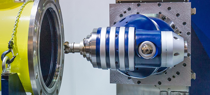
ISCAR is expanding the TANGSLIT slitting cutters by adding TGSF-JHP cutters with coolant channels directed to each and every cutting edge and SW/S-JHP driving shanks that can convey the coolant to the cutters.


Coolant channels directed to each and every cutting edge facilitates efficient cooling to prevent built-up edge, substantially prolonging tool life. With very efficient chip disposal, improved surface finish, and advantages for both low (10 bar) and high (340 bar) coolant pressure, the new slitting cutter represents an ideal solution for machining high temperature alloys and stainless steel, offering higher productivity as cutting speed can be raised up to 50%.

The TGSF-JHP cutter features 63-125mm cutter diameter and 3.0 and 4.0 mm slitting widths. The SW/S-JHP shank features 25.0 and 32mm shank diameters and shell holder with 32.0mm adaptation.

For more information, contact ISCAR South Africa – Tel: 011 997 2700

Radan 2017 Heralds Start Of Major Engineering Functionality

This 3D engineering of parts is becoming increasingly important. It will enable manufacturers to break assemblies down from CAD systems, into their constituent components and fully understand everything about them.

Product Manager Olaf Körner says, “we are on the verge of reorganizing how manufacturers will be using Radan in future and important updates to Radmanager in the new edition are the first steps towards this.”

Developers are working on separating Radan into two distinct aspects; first, traditionally creating NC code to drive CNC machines and second, what they call engineering of parts. Radmanager’s strength is that it creates nests without the user necessarily needing to know where the parts come from, what the order numbers are or which customer they are for.

“To achieve this, it relies on the parts being completely ready for nesting,” says Körner. “And that means more than just having flat parts with the right geometry. We need to know as much as possible about the parts – whether they can be cut on any machine tool and the cycle times for all of those solutions. For example, it may be feasible to cut a part on either a laser or water jet, but while it would take only minutes on the laser, it may take two hours on the water jet.

“In Radan 2017, Radmanager’s ability to manage both 2D and 3D engineering of parts is the precursor to the entirely new forthcoming engineering system for any type of parts, including 5-axis laser-cut sheet metal, tubes, flat and bent.”

The forthcoming Radquote, which is now available as a preview will be demonstrated at exhibitions and pilot customer sites ahead of its official launch. Radquote will also rely on engineered parts.

“This 3D engineering of parts is becoming increasingly important. It will enable manufacturers to break assemblies down from CAD systems, into their constituent components, and fully understand everything about them.”

2D CAD files can also be imported automatically into Radmanager now, without the need to convert them.

CAD/CAM Updates

Radan 2017 addresses danger of scrap flying off, sliding under the sheet, or damaging the tools on punching machines, by flagging up where floating scrap will occur. The Automatic Order Style Editor now shows graphically what the program is going to do, enabling users to home in on a particular operation to make changes. This is seen as a major improvement on the previous text-based system.

Still with punch presses, Radan 2017 configures machine tools with all available cutting tools, so that new customers have commonly used tools immediately available.

3D

A side panel was introduced in a previous version of Radan which aids navigation around complex assemblies, but there was still a need to travel between the two. A new facility in Radan 2017 allows the user to stay with the model and to immediately switch between front view, side view, top view etc.

The graphics drawing has been speeded up. As an example, Körner explains that in earlier releases, deleting all screws in an assembly may take a while after they were selected, but now he says the software will always deliver a quick and consistent frame rate. The 3D function also supports modern graphics cards more efficiently, improving performance on tablets.

The process of updating information between Radbend and Radan 3D has now been automated. “A design is analysed in Radbend and then the bend information it provides fed back into the 3D model. This used to be a process that the user performed in a number of steps. Now, once the part has been identified, it’s a simple mouse click to update the information.”

Nesting

Improved algorithms have led to an important enhancement of Radan’s powerful nesting capabilities. “Continuous effort is applied to further strengthen the nesting engine to achieve a better fit and therefore, a potentially better material yield.” With an increasing number of users adopting project nesting, a new reporting engine ensures users can easily customise the content and design of their reports.

It is also easier now to create nest projects, thanks to the new template function. Körner says, “existing project settings can be stored with a given name and recalled at any time. “Even creating nest projects for the same machine tool sometimes required repetitive work, but now everything the user needs will be there, saving quite a number of steps.”

Profiling

Autotooling routines are now more efficient in placing tags, or microjoints, for common cutting, and the foil cutting function has been extended to scrap, ensuring that where sheets are covered with a protective foil for laser cutting, clean cuts can be made for scrap, too.

Radbend

Radbend now highlights where holes are at risk of deforming by being close to bends.

The operator can switch between Design and Result Values. “This is particularly valuable where Radbend shows the end result of a radius, for example, may be different from how it’s designed. Selecting which values gives the user more control over the finished bend, depending on whether it’s vital that they stay with the design values, or if the end result values are acceptable.”

For the first time, the user can now check with different maximum allowed force for the pre-bend and the hemming operation done with same tools.

Improved communication between 3D and 2D parts ensures that Radbend can now link to the 2D flatblanks created by Radan 3D. It also means that with more information going to the flatblank, 2D bends can easily be seen – the tooling and sequence number, as well as the radius, angle and setback.

Radbend now supports the new user interface, Touchpoint TruBend, which combines the advantages of multi-touch technology with industrial control…as all Trumpf pressbrakes will move to this state-of-the-art controller.

Radtube

While Radtube has traditionally been used for simply cutting tubes, it can also program any extruded shape for tube cutters, including I-beams, H-beams and C-beams, along with L-shaped profiles. “Because cutting a round or square tube is completely different from working with more complex beams and profiles, we’ve assisted the user with this by vastly improving automation and support.”

Summing up Radan 2017, Körner says the items of new and enhanced functionality provide immediate improvements for sheet metal manufacturers, while underlining the intention to continue investing heavily in the software.

“Developing Radan to engineer and fully analyse parts in this way is the biggest step forward we’ve ever taken. The future is very exciting, as the level of automation we’ll be able to achieve is phenomenal.”

For more information, contact Stillam CNC Programming – Tel: 011 663 2600

Edgecam 2018 R1 Reduces Regeneration Time

It is this latter update which is seen as being the most important for manufacturers. When a user makes an edit to an existing command, Edgecam 2018 R1 will not automatically regenerate the remaining instructions.

Edgecam Brand Manager John Buehler says when editing a tool command, there will now be no regeneration if the alteration does not affect the corresponding cycles with aspects such as coolant or high-speed.

Two new items of functionality in the Roughing Cycle provide time savings in the milling, turning and MTM environments.

“Detect Undercut Stock enhances the already powerful stock detection command, by analyzing previously undetected areas of stock. This option helps to avoid fresh-air cutting, reducing machining time – in some cases by up to half.”

The game-changing Waveform Roughing Strategy now gives users the ability to determine the radius size when using the helical approach option, by simply entering maximum and minimum values, which will aid the tool’s entry into the component.

Automatic collision detection has been added to the Rough Turning Cycle. In previous versions of the software, it was necessary to manually apply profile extensions to avoid collisions. Buehler says as users no longer have to do it themselves, time will be saved in initially creating the CAM instructions. “An additional benefit is that this new function can be used to produce safer toolpaths in Strategy Manager.”

Edgecam 2018 R1 provides support for Deep Hole Drilling – also known as Gun Drilling. The new strategy empowers the user to control entry, exit and intermediate drilling conditions. “This will be particularly important where specialized Gun Drilling tools are used and the process requires absolutely precise NC code.”

The Profiling cycle used in both milling and turning, now has two new items of functionality. A Spring Cuts field has been added to the Multi Passes tab, which means tool deflection can be removed where necessary, by adding extra neutral passes, known as Spring Passes. This will be used typically when machining hard materials…repeating the profile pass can result in improved accuracy and surface finish.

And secondly, the new Adjust Feedrate on Arc command improves cycle time calculation. In previous editions of Edgecam, the postprocessor adjusted circular interpolation feedrates, which gave correct NC output, but not the best cycle time calculation.

Support for JT Open files is incorporated for the first time. This is a lightweight 3D model format developed by Siemens PLM Software. “As this file format is expected to become increasingly popular, more and more Edgecam users will benefit with the files now being supported in the Solid Machinist for Parasolid license. And there’s also support for AutoCad 2018 DWG/DXF files.”

An Editing Manual Milling function provides for editing a manually created milling feature, instead of having to recreate an entire feature when extra edges are required. This is expected to give considerable time savings to Solid Machinist users.

First released in Edgecam 2017 R2, the Edgecam Inspection module has been significantly enhanced, which Buehler says brings many new features to the software. “Considerable progress has been made with the postprocessor development and NC output, through new Code Wizard options. This includes support for Fanuc macros.

“Users now have full control when editing an Inspection feature, including a calibration technique. They can also determine both feature and properties characteristics.”

In addition, the Move Point function within the Inspection module has two further options: Fixed Axis and Fixed On Surface, giving the ability to align a measurement point along a fixed axis, or a solid face. And the Plane Feature command has been enhanced enabling users to choose to evaluate flatness on more than four probe touches.

Edgecam 2018 R1 continues the evolution of updating cycle dialogs with pictures and context-sensitive help, by updating the B-Axis Contouring Cycle and 3- and 5- Axis cycles. This not only assists experienced users to easily interpret an infrequently used command, but also helps less familiar users to rapidly understand fundamental functionality.

Another new feature that delivers significant time savings is the Pass Boundary To Cycles function, in the Feature Properties window. An improved toolpath is generated when the user engages Current Stock and picks a solid feature. Rather than use the stock limits, which can sometimes lead to unwanted passes, the toolpath is now clipped back to the feature’s natural boundary … particularly useful when creating automatic toolpaths in Strategy Manager.

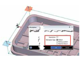
Buehler says the new release includes several user experience enhancements, one of which is the improved visibility and consistency of the Datum Workplane marker. “The new datum is more prominent and will change appearance to signify its usage – default, mating location, or machine datum. This is particularly useful when working with multiple component parts, on tombstones and multi-face machining.”

Finally, additional functionality has been added to the B-Axis Contouring Cycle, which was introduced in the 2017 R2 edition. “Maximum Angular Increment will improve the surface finish by refining the NC output, while machining complex turned profiles,” concludes Buehler.

For more information, contact Stillam CNC Programming – Tel: 011 663 2600

MV-R Connect Wire-Cutting Machines With New Generation Control

A new option that displays the output of numeric values as easy-to-read graphics – much like in an aircraft’s cockpit – is now available.

Hans-Jürgen Pelzers, sales manager Europe, explains, “operation has to be simple, quick and flexible so that the user is able to achieve precise results with little effort – even when working to the highest standards.” The new manual control box of the MV-R Connect features a bright, user-configurable display and is equipped with all the important functions. With a freely rotating and pivoting 48cm multi-touch display, the operator can comfortably make settings according to his needs.

Thanks to the built-in cost and performance monitor, the operator can analyse machine profitability and uncover reserves to optimise processes and boost efficiency at all times. Diagrams depict operating costs and output. All operating material statuses and maintenance cycles can be called up at a touch – and if desired, read out. The machine comes with a network connection, USB, FTP, DNC and open data interfaces, and can be linked up to existing production planning and analysis systems.

In tune with the anticipated future requirements of Industry 4.0, the abundance of processable data available with these machines ensures transparency throughout the production stages. Intel Security is pre-integrated to provide security. Product Manager Stephan Barg says, “transparent production is now possible and is proving to be appreciably more profitable and cheaper with the MV-R Connect series.”

The newly designed job planner makes it possible to simply bring forward urgent jobs, with automatic saving of the parameters of the interrupted jobs; meaning work can be resumed later on, immediately from the point of interruption. Countering the shortage of skilled labour, the control guides less experienced users through the cutting process step-by-step and thereby teaches them the points to bear in mind while they are working.

Expert mode takes a more direct approach, and the flexible configurability of the control interface makes it possible to attune the machine entirely to typical applications and the operator’s personal focus. The MV1200R Connect and MV2400R Connect premiered at EMO in September 2017 and are expected to be available from November.


For more information, contact WD Hearn – Tel: 021 534 5351

AgieCharmilles Cut E 350/600 Wire-Cutting EDM Machines


Solutions to advance customers’ performance and productivity, secure their processes and accelerate their time to market are engineered into GF Machining Solutions’ AgieCharmilles CUT E 350/600 wire-cutting EDM machines.

Driving the machines’ accuracy and efficiency are onboard collision protection, new builtin machining strategies and flexible job management, within an easy-to-use humanmachine interface (HMI). The machines’ ergonomics and improved design minimize their workshop space requirements, and their high rigidity allows accurate cutting of large and heavy parts. Their compact, spacesaving layout ensures efficient workshop integration, and the drop door system allows easy, convenient access to the working zone.

The CUT E 350/600 machines boast a reliable wire circuit system for perfect unrolling that does not disrupt the EDM process during machining. The filters, positioned side by side, make maintenance fast and easy, and ease of use is also a factor in the remote control, designed for one-handed use – a real help in fine tuning workpiece preparation.

Integrated glass scales preserve long-term, repeatable accuracy, require no recalibration, and eliminate classical screw system errors related to backlash and wear. A large, 25kg spool is available to extend running hours and allow continuous production.

The machines’ AC CUT human-machine interface features powerful job management. Information about geometries, machining processes and command programs are processed in one file, so jobs can be transferred between CUT E series machines and all modifications are managed automatically. More than 10 automated measurement cycles are available to ease workpiece preparation, and with standard, onboard AC CAM Easy, the operator can prepare an ISO file and post-process it into a job during machining.

Efficient production is at the heart of the modern Intelligent Power Generator (IPG). Its integrated technologies boost cutting speed, precision and surface quality. The CUT E series machines can use dedicated wire for decreased part costs and increased turnover, and the POWER-EXPERT module decides the optimal power to send in the wire – especially efficient for stepped parts. The corner strategy module automatically adjusts parameters during change of direction to produce sharp angles and small radii. Integrated speed dedicated processes can reduce cutting time up to 18 percent compared to standard machines, and the CUT E series demonstrates its versatility by offering cone cutting capability up to 30 degrees over 45 mm.

The Intelligent Collision Protection (ICP) on the X, Y and Z axes eliminates costly collision-related downtime and protects your machine and workpieces, so your machine operators can work with confidence. Unique on the market and arising from GF Machining Solutions legacy of more than 60 years of EDM expertise, ICP detects even the slightest abnormal forces and halts X, Y or Z axis movement in order o avoid collisions and the costs and damages than can follow a collision. At the same time, the machines’ ThermoCut module provides for successful, efficient threading by preparing the wire properly before threading.

For more information, contact Retecon – Tel: 011 976 8600

Studer – Experts In Internal And Radius Grinding

New market segment opened up

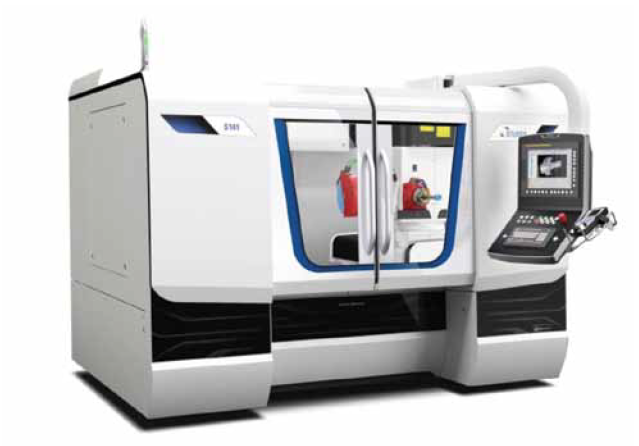
In the past, this range of parts was successfully covered by STUDER universal internal cylindrical grinding machines CT750 and CT960. With its market entry, the new S121 radius grinding machine will now take over the range of applications of the CT750, while the S131 has been designed for the previous component range of the CT960. New with the S141 radius grinding machine is that the machining of larger work pieces is also now possible. For the user, this means in figures – the swing diameter above table is 250mm for the S121, 300mm for the S131 and 400mm for the S141. External diameters up to 160mm can now be machined with an external grinding wheel 250mm in diameter. The maximum length of parts including clamping device is 300mm for all three radius grinding machines, and the maximum work piece weight including clamping device is 100kg.

There are good reasons why STUDER is replacing the successful CT models, which translate into increased customer benefit. First and foremost, a higher level of technology has been achieved with the new radius grinding machines. This is evident in the machine bed, which now comprises of Granitan® and thus offers higher dampening levels, thermal stability and guidance accuracy. It is also reflected in the StuderGuide® guideway and drive system with linear motors, which features high wear resistance, a long working life and high dynamics (interpolation possibility).

The main benefit which customers can derive from the new machines is the extended range of parts possible due to the larger size of the machine, and the new dressing concept which, thanks to the new arrangement on the B-axis (simultaneously swiveling work piece table) is not only simpler, but also offers greater thermal stability and mechanical rigidity. The fact that the new S121, S131 and S141 are now also manufactured according to the Thun modular principle also means non-variable parts in maintenance and service and consequently a higher availability of service technicians. It also means harmonization of the components and with the new design and improved ergonomics, an increase in the machine’s value.

The S141 radius internal cylindrical grinding machine for larger work pieces has a swing diameter of 400mm and grinds work pieces up to 300mm.

Powerful software

Special mention should be made of the StuderSIM software in regard to the new radius grinding machines. With this software, STUDER answers the question of what an operator needs in order to be able to machine complex parts – often in a single clamping. The answer – an assistant, with which work pieces – derived from a drawing – can be completely defined, all necessary geometric data for the grinding cycles can be generated and with which the grinding process can be checked and visualized by means of simulation on a PC or on the machine; StuderSIM is this powerful assistant. It is complemented by hardware which features the previously mentioned Granitan® machine bed and the StuderGuide® guideway and drive system with linear motors. It also includes X and Z-axes in a cross-slide arrangement as well as a cross slide, which in the case of the S121 can either take one spindle, two spindles in parallel or two spindles on a hydraulic turret and in the case of the S131 and S141 comes with a 4-position turret with direct drive.

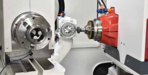
The machines are also equipped with a work-head on a simultaneously swiveling B-axis, a dressing spindle or a fixed dresser on the B-axis and a measuring probe on the grinding head. Other new features are, finally, the enclosure and the control console in the STUDER design.

The S121, S131 and S141 radius grinding machines differ from the universal cylindrical grinding machines of the same name in a number of technical details. The B-axes of the radius grinding machines are set up simultaneously and offer interpolation (from -60° to +90°), while the universal cylindrical grinding machines have a swiveling table, which can be positioned from -10° to +20°. In addition, the spindles on the radius grinding machines are arranged at the rear of the turret, while this is the other way round on the cylindrical grinding machines – they are at the front. There are also differences in the dressing concept. The radius grinding machines have the dresser on the B-axis, while the cylindrical grinding machines are equipped with two swivelling dressers. Last but not least, the S121 to S151 cylindrical grinding machines use the STUDER operating system StuderWIN, while the new radius grinding machines use the StuderSIM operating system.

Platform is complete and rounded

With the market entry of the S121, S131 and S141 radius grinding machines, the platform of STUDER internal cylindrical grinding machines is now complete and rounded. In addition to the new radius grinding machines, the platform includes the simple S110 and S120 machines, the S121 to S151 universal internal grinding machines and the S122 production internal grinding machine. Five machines have been replaced (S120, S145, S151, CT700, CT900), enabling four new market segments to be opened up. The S121 universal internal grinding machines are small machines for a large application range, the S122 production internal grinding machine is a machine for large component output and high availability and the S141 and S151 universal internal grinding machines (700 and 1300mm) are machines for long work pieces. Finally, a fourth market segment is opened up with the new S141 radius grinding machine for parts up to 400mm in diameter.


For more information, contact Retecon – Tel: 011 976 8600

Makino Updates MMC2 Automated Pallet-Handling System

New design configuration enables up to 95 percent machine utilization rates in 5-axis machining applications

Automation is essential in helping manufacturers achieve maximum return on investment (ROI) from their machine tools. Makino is pleased to share the availability of a new design configuration for its popular MMC2 automated pallet-handling system which enables full compatibility with the company’s uniquely designed a61nx-5E 5-axis horizontal machining center. Together, these technologies offer a powerhouse combination of processing speed and flexibility, giving aerospace manufacturers more control over their workflow and the ability to adapt quickly to customers’ just-in-time needs for complex, multi-dimension part applications.

The updated MMC2 retains the same modular design and capabilities of its predecessors, but with a new pallet-transfer interface on the system’s rail-guided vehicle (RGV). This interface can handle the unique pallet designs used on the a61nx-5E. As a result, manufacturers are able to achieve spindle utilization rates upwards of 95 percent to further maximize the value of their a61nx- 5E investment.

“Based on feedback from current a61nx- 5E owners, we’d come to realize that the machine’s productive capabilities were so high that most operators were struggling to keep their machines fed with raw materials,” said David Ward, product marketing manager at Makino. “While we see this as a good problem to have, it is still an issue that we wanted to address. By providing this optional pallet interface on the MMC2, we’re able to help manufacturers keep up with the productivity rates of the a61nx-5E to get the most value out of their investments.”

Capacity for Future Business Development

The MMC2 is designed to accommodate up to 15 machining centers and four worksetting stations into a single system. Each system can hold up to 200 pallet stockers – stacked either one, two or three layers high – with a virtually unlimited variety of parts and fixtures.

The system’s RGV is supported by a floor rail and upper-guide rail for enhanced stability and simultaneous, high-speed movement. The system’s work-setting stations (WSS) provide easy access for operators to load and unload parts either by hand or crane. Each WSS has 180-degree pivoting doors to save space and prevent a cluttered work area. The MMC2 can be equipped with optional workpiece washing guns.

Users of the MMC2 frequently report spindle utilization rate improvements of up to 95 percent, leading to dramatic increases in production without adding staff or equipment. The MMC2 system permits users to virtually eliminate part setup time, reducing non-valueadded time in their machining operations. By providing a continual flow of parts to the a61nx-5E, the system can run for extended periods unattended, including over nights and weekends.

Flexible Scheduling and Cell Management

The updated MMC2 retains the same Microsoft Windows-based MAS-A5 control software, which helps maximize production output while monitoring multi-machine production requirements. The MAS-A5 main PC hard drive stores and manages all NC programs for optimum machine utilization, including NC programs that exceed CNC memory. With these storage capabilities, there is practically no limit to the number of fixtures and associated process sequences and offsets that can be logically assigned to an individual pallet.

Tool data, both in and out of the a61nx-5E machines, can be accessed and modified from the MAS-A5 user interface. A variety of file formats for tooling and part information are supported and can be displayed to assist with part loading/unloading and tool-setting operations. The Tool-Life Predict function enables the MAS-A5 to gather tool-life data per NC program. When a request is opened, this function informs the operator of how long a tool is used in each NC program execution, as well as how many spare tools per machine are required to finish any work that is currently loaded or awaiting processing at the time that the request was placed. The MAS-A5 then schedules work only for the machines that meet tool-life and availability requirements for the desired process sequence. Interfacing with a tool presetter also reduces errors by automatically capturing tool-offset data, which can be transferred from the presetter to the MAS-A5 system control.

Standard control features include in-cell production scheduling, equipment status monitoring, NC program management and on-board reporting. These capabilities enable the MMC2 to assign work and initiate operations automatically, based on machine and material availability, using maximum spindle capabilities and monitoring all automated procedures.

For more information, contact Rothco – Tel: 011 970 1930

Holographic Measurement Technology At Production Speed

Digitale Holografie im Produktionsakt; Joseph von Fraunhofer Preis 2017; JvF-Preis 2017;

Fault tolerance in automobile production is increasingly diminishing. Until recently, this presented suppliers with a problem: There were no sufficient methods for detecting micro defects during production.

Visual inspection was the solution of choice, but this is not suitable for in-line measurements in the production process. By developing digital holography to become suitable for production, researchers at the Fraunhofer Institute for Physical Measurement Techniques IPM in Freiburg, Germany have resolved this dilemma. Digital holography makes it possible to fully inspect all parts – in a matter of seconds.

Sometimes every thousandth of a millimeter counts – such as with components for the automotive or aviation industry. In order to determine whether the individual component is fault-free and dimensionally stable, digital holography would be the method of choice. However, this method has so far been slow and sensitive to vibrations. It was therefore not suitable for production environments, and only samples could be tested.

Fast, solid results

Three researchers from the Fraunhofer IPM – Dr. Markus Fratz, Dr. Alexander Bertz and Dr. Tobias Beckmann – have now brought the process of digital holography out of the laboratory and into the production hall. “We have been able to eliminate all the disadvantages and have therefore, for the first time, developed a system that allows one hundred percent inspection in production,” says Beckmann, who heads the project together with Fratz. “Our system can measure centimeter-sized rough objects in fractions of a second with micrometer accuracy, thereby compensating for disturbances, such as vibrations.” This allows for in-line measurements during the production process for the first time. Instead of taking samples, as before, each individual part can therefore be checked for dimensional accuracy and, at the same time, for the smallest defects. The challenge the three researchers faced was anything but easy to solve. “The search for defects is like trying to measure the shape of a 25-meter-high football stadium from a height of 300 meters so accurately that you can find the footprint of a baby in the grass – and in fractions of a second, even if the stadium is shaken by a light earthquake,” Fratz explains.

Laser waves of different wavelengths and intelligent algorithms

The system can measure centimeter-sized rough objects in fractions of a second with micrometer accuracy – even under disturbances, such as vibrations. © Fraunhofer IPM

But how did the researchers manage to succeed? Instead of interferometrically measuring the object with laser light only at a single wavelength, they illuminate it successively with laser beams of different wavelengths and assess the resulting images in relation to one another. Another highlight is the evaluation algorithms. The researchers have parallelized them so as to take full advantage of the performance of a highend graphics card. As a result, the system is so fast that it can precisely measure objects to the micrometer within fractions of a second. “For highly accurate threedimensional measurements, our system is the fastest available on the market worldwide,” says Bertz, Group Manager at the Fraunhofer IPM. This speed, in turn, makes the system robust and comparatively insensitive to interferences such as vibrations. This is comparable to taking a photograph: the shorter the exposure time, the less the image blurs.

Production without risk

For Werner Giessler – a medium-sized company that manufactures components for diesel injection systems – the process was a kind of salvation. From its customer, Bosch, the company was commissioned to start delivering 10 million components per year instead of the previous 6.5 million and all without a single defective part. With visual inspection, this would have been impossible. With the help of digital holography, though, the medium-sized company was able to accept the contract. “I’m not enough of a risk taker to do without this technology,” says Managing Director Thomas Giessler. “Companies that have not learned to inspect the quality of their parts will soon disappear.” The system is already integrated into the production process.

Markus Fratz, Alexander Bertz and Tobias Beckmann have received the Joseph von Fraunhofer Prize for the development of production-ready digital holography. The jury justifies the award by mentioning, among other things, “the outstanding scientific work and the first-time presentation of the industrial suitability of the process”.

Machinery That Repairs Itself

In the EU-funded project SelSus, Fraunhofer scientists are collaborating in a consortium with partners from research and industry to develop maintenance technology capable of forecasting machine downtimes in production before they occur.

This allows plant managers to rectify faults before the machine breaks down. The system even corrects some defects automatically.

Unforeseen machine failures during ongoing production – plant managers dread them, technicians detest them and managers just sigh and factor them in. Such incidents prompt frantic repairs, drive up costs, adversely affect delivery reliability and ultimately weaken companies’ competitiveness. Yet often the problem is only a small defect or normal wear and tear. However, if left undetected, these can lead to major disruptions and production downtimes.

What would be helpful is a diagnostic procedure capable of monitoring the status of all components in the production line, identifying problems and weak points and informing the responsible employee in a timely manner. Based on what’s known as a decision-support system, maintenance personnel can then reach a decision and take targeted action to repair the defect. Ideally without having to interrupt production.

Precisely this is one of the underlying ideas, albeit not the only one, behind the ambitious SelSus project within which the Fraunhofer Institute for Manufacturing Engineering and Automation IPA is currently researching. “The aim is not just to monitor the status of the machines and components. Using intelligent software and sensor networks, the plan is to detect potential weak points or signs of wear and tear early enough for the system to be able to predict potential malfunctions,” explains Martin Kasperczyk from Fraunhofer IPA. The developed diagnostic models also directly provide suggestions or recommendations on how to rectify the problem. Project partner Electrolux in Pordenone, Italy, uses such a decisionsupport system. The system is capable of predicting with a certain probability potential failures on a press for washing machine facings and of diagnosing actually occurring malfunctions. The data needed to monitor the machine status is partially provided by sensors. They measure values such as energy consumption, temperature, oil pressure, particles in the oil or vibrations. Fraunhofer IPA and the participating consortium have also proved that the technology functions reliably in practice.

The system repairs itself

The system is even capable of sending control impulses to individual machines. A welding control on which a sensor has failed, for instance, can continue to work almost seamlessly in a secure mode, without any serious disruptions. The capability for selfrepair and sustaining production has also given the project its name. The full project title of SelSus is Health Monitoring and Life-Long Capability Management for Self-Sustaining Manufacturing Systems.

However, first a number of technological hurdles had to be overcome. Kasperczyk says, “one of the biggest challenges was analyzing the flood of data. After all, we’re talking here about predicting malfunctions or breakdowns of machines with a high degree of reliability. You don’t get there just by programming a couple of algorithms.”

Bayesian networks and sensor data

The experts are putting their faith in Bayesian networks. A Bayesian network is a mathematical model that can be used to compute the probabilities of a certain event or state occurring. The model represents a set of variables and their conditional dependencies. With the help of the data collected by the sensors, the software for example computes the probabilities of a specific high-stress cable breaking in the near future and, where applicable, signals that it should be replaced.

But the SelSus software relies not only on sensors. It also takes the technical characteristics of the machine and its performance parameters into account. This data has to be captured during installation and configuration of the system. Moreover, an extensive test run tells the system how the machine and its components behave in continuous operation and under load. Only then is it ready for use. The software also registers new data, for instance as a result of machine upgrades or deterioration in performance due to wear, enabling the system to learn.

The complexity of the SelSus concept is also evident from the fact that the software even interacts with operators by analyzing the causes of potential or existing malfunctions and proposing an appropriate course of action.

A system with self-healing capabilities from Coventry

Project partner The Manufacturing Technology Centre from Coventry, UK, has created a system with self-healing capabilities. In an engine production plant, a dispenser is attached to a robotic arm by means of vacuum. If the dispenser encounters resistance, rather than snapping off, it reacts flexibly. It loses the grip produced under vacuum and drops a few centimeters until it is stopped by springs. The springs then draw the dispenser back to its original position. Subsequent calibration ensures the tool is in the correct position – and after the brief interruption, the work process continues.

Politicians have long recognized the potential offered by the technology. SelSus has received nearly 5.4 million euros in funding from the European Commission. In addition to Fraunhofer IPA, the project consortium includes renowned industry partners such as automaker Ford, household appliance manufacturer Electrolux, welding technology provider HWH Hamburg and automation specialist IEF-Werner. Other participants are universities, such as Loughborough University and the Instituto de sistemas e Robotica, or ICT providers including HUGIN EXPERT, Advanced Data Processing or Inotec, to list but a few.


Large DMG MORI 5-Axis Machining Center Installed At Titanus Slew Rings

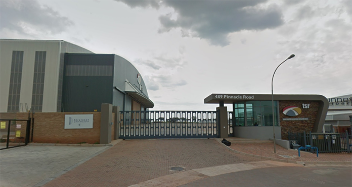
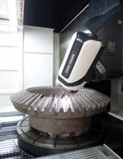
The largest 5-axis machining center ever sold to a South African customer by DMG MORI has recently been installed at Titanus Slew Rings (TSR) in Elandsfontein, near Germiston.

The machine, a DMU 210 P 2nd generation, supplied by local machine tool merchant Retecon, weighs a staggering 60 tons and features a work area of 2,100 x 2,100 x 1,250 mm, while being capable of handling a maximum table load of 8,000 kg.

Titanus Slew Rings was founded by Renato Casagrande in 1975 as a general engineering concern, and then named Titanus Engineering. Excellent workmanship, expertise and outstanding service to the highest standard ensured the company’s steady growth, twice requiring a move to larger premises.

In 1985 a strategic decision was taken to focus and further specialize production facilities towards the manufacture and reconditioning of slew bearings. The company was renamed Titanus Slew Rings and moved to the wholly owned new premises in Elandsfontein. TSR is a privately owned, family controlled business, ensuring flexibility and fast re-alignment of resources towards meeting customer requirements.

Director Marco Casagrande says, “at Titanus Slew Rings we are committed to the implementation of the latest innovative technologies in slew bearing manufacture. Profits are continuously re-invested in new capital equipment and process technologies in order to maintain the highest levels of quality.


“We currently have ten CNC vertical borers capable of machining slew bearings and components from 500 mm in diameter to 6,300 mm in diameter with some of the vertical borers featuring live spindles for maximum efficiency.

“With over ten gear cutters capable of cutting internal and external gears, we are easily able to meet the capacity of our slew bearing range. In addition, we offer gear cutting services to our customers, including the manufacture and reconditioning of girth gears. The maximum size external gear we can gear cut is 7,000 mm in diameter, and on the internal range we can cut a maximum of 4,000 mm in diameter.

“Continuous investment and upgrading of our machine shop is key to our ability to provide our clients with the highest quality products, and that is the reason why we just purchased the 5-axis machining center from DMG MORI,” explains Casagrande.

TSR last month invited customers and the press to an open-day viewing of the new machine.

The modular concept of the DMU 210 P 2nd generation offers an ideal solution for every application – starting with an innovative wheel magazine that can accommodate up to 303 SK50 tools while still requiring only very little floor space and on to include the most extensive range of spindles. The offer ranges from the powerMASTER motor spindle with max. 1,000 Nm to the torqueMASTER gear spindle with up to 1,800 Nm and on to include the speedMASTER spindles with their impressive speeds of up to 30,000 rpm.

The DMU 210 P 2nd generation features rapid traverse rates of 60m/min, 40m/m and 40m/m on XYZ.