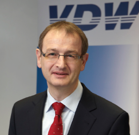
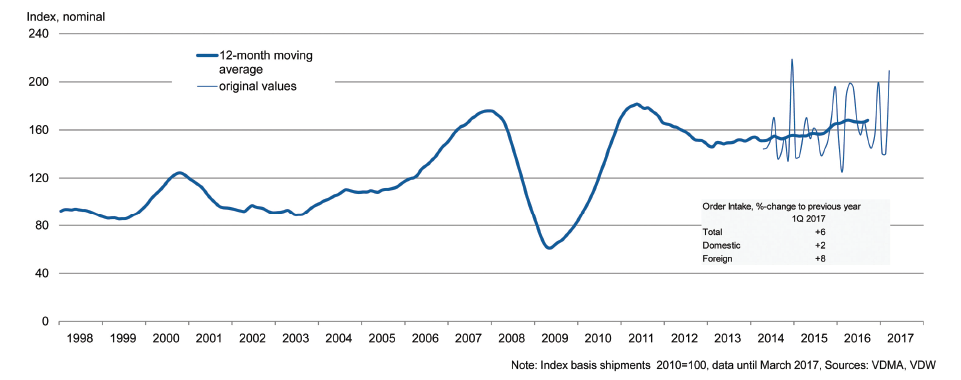
“Orders received by the German machine tool industry have therefore been stronger than expected,” said Dr. Wilfried Schäfer, Executive Director of the VDW (German Machine Tool Builders’ Association) in Frankfurt am Main, commenting on the result.
Dr. Wilfried Schäfer, Executive Director of the VDW (German Machine Tool Builders’ Association).
International demand remains consistently high. The euro countries represent a reliable market. There was a disproportionately high increase of 23 percent in orders for machine tools from there in the first quarter in comparison to the same period last year. “Furthermore, the increase in demand from the key Chinese market is now broader based,” reported Schäfer. Orders rose last year by more than twenty percent, primarily due to large international automotive industry projects in China. The strong development has continued, however, in the first quarter of 2017.
There was a 13 percent increase in metal forming technology orders. This rise in demand came both from home and abroad. Machining equipment orders, however, which represent about 70 percent of the total, only rose by 3 percent. The main source of growth here was foreign markets, which posted an increase of 6 percent. Domestic demand, by contrast, fell by 4 percent.
“The German machine tool industry continues to perform stably and at a high level, undeterred by the many crises and uncertainties affecting different parts of the world,” said VDW Executive Director Schäfer.
Airbus is developing a full spectrum of new Cabin Enablers for customers of its flagship A380 airliner.
The latest is the New Forward Stairs (NFS) option which was presented at the Aircraft Interiors Expo (AIX) in Hamburg. Together these cabin enhancements will make this very efficient and comfortable airliner even better. Overall cabin optimization is expected to result in the freeing-up more cabin floor space for around 80 additional passengers. This would bring airlines significant additional revenues.
Dr. Kiran Rao, EVP of Strategy and Marketing at Airbus Commercial Aircraft said, “continuous improvement of our products is our daily work. This new package for our A380 customers is a smart way to meet airline needs while improving the A380 economics with additional revenues and innovating in passenger comfort.” Rao added, “only the A380 has the economies of scale and development potential to efficiently solve the problem of increasing congestion at large airports while providing the best comfort for passengers. The aircraft can also serve fast growing markets and airlines regional airports, so we are adapting the aircraft to meet evolving market needs.”
With this latest proposal of the NFS option, the package of new cabin enablers for the A380 now comprises the following – New Forward Stairs – 20 more passengers (Business, Premium Economy & Economy Classes).
The NFS involves relocation of the forward stair from Door 1 to Door 2, and combining the entrance of the NFS to the upper deck (going up), with the adjacent staircase to the lower-deck crew-rest (going down). The NFS would make room for up to 20 additional passengers. Combined Crew- Rest Compartment (CCRC) – three more passengers (Premium Economy).
For the CCRC, the existing flight-crew-rest (behind the cockpit in the mezzanine area at Door 1) is moved down and combined with the cabin crew rest on the lower deck. This innovation frees space for three extra Premium-Economy passengers at the front of the main-deck. 11-abreast 3-5-3 economy layout on the main-deck – 23 more passengers (Economy Class).
Thanks to an innovative seating concept developed by Airbus and its seating partners, Airbus is able to maintain an 18inch seatwidth while offering airlines an 11-abreast Economy Class on the main-deck in a ‘3-5-3’ configuration. This enables an increase in capacity of 23 seats – adding significantly to the A380’s revenue-generating potential.
New Aft-Galley Stair Module (AGSM) – 14 more passengers + two food trolleys.
The AGSM involves the redesign of the rearstair from a spiral agreement to a straight/ square one. On the main-deck, this allows valuable storage volume for galley modules. Overall the AGSM provides space for 14 more revenue passengers plus two extra food trolleys. Upper-deck sidewall stowage removal – 10 more passengers (Business Class).
The option to remove the sidewall stowages on the upper-deck increases the wall-towall cabin width at foot-rest height – which makes space for up to 10 more business class seats / beds when an angled herringbone arrangement is used. Nine-abreast Premium Economy on the main deck – 11 more passengers (Premium Economy).
The A380’s generous main-deck cross section – significantly wider than any other commercial airliner – is allowing seat manufacturers to optimise their Premium Economy (PE) seat designs to create the industry’s most efficient and comfortable PE layout possible. This layout enables 11 more PE seats than in an eight-abreast layout.
EMO Hannover 2017 provides inspiring ideas for lightweight construction
Ultra-high-strength materials are highly popular not only in aircraft and automobile manufacturing, but also in the mechanical engineering sector, because they are often comparatively light and at the same time very sturdy. Machine tools, however, not infrequently come up against their physical limits when processing these materials. This can be remedied by using structural parts for machinery that are made of lightweight fibre-reinforced materials. This entails mastering some serious obstacles, as evidenced by an as-yet-uncompleted research project at the Fraunhofer Institute for Production Technology (IPT) in Aachen which will also be on show at EMO Hannover.
CFRP replaces steel for enhanced dynamics
The researchers in Aachen usually adopt a holistic approach to optimizing designs. In other words: they consider the machine’s design as a coherent whole, thus also including the development of important drive elements in the machine tool. They have currently joined forces with a machine tool manufacturer to examine how an innovative machine component for vertical movements (Z-axis) made of carbon-fibre-reinforced plastic (CFRP) behaves in a machine tool and how the Z-slide can be optimized.
To quote Christoph Tischmann, Branch Manager of MAP Werkzeugmaschinen, “so as not to have to compromise on the dynamics, we were looking for a way to compensate for the greater weight by using a CFRP variant.” Photo: MAP Werkzeugmaschinen GmbH
“We began development work on the CFRP slide in 2013,” relates Christoph Tischmann, Branch Manager of MAP Werkzeugmaschinen from Magdeburg. “We already possess plenty of experience with linear and rotary axes, for machining aluminium, for instance. But for high-strength materials like the titanium alloy Inconel they do not possess the requisite drive power.” So MAP decided to develop a machine tool with very powerful drives: for example, 55- and 72-kilowatt spindles (torque 210 and 273 Newtonmetres respectively in S1 or S6 mode) are now used, which are significantly heavier and larger. “So as not to have to compromise on the dynamics, we were looking for a way to compensate for the greater weight,” explains Tischmann. “That’s why we opted for the CFRP variant.” By way of comparison: the machine tool used to operate in the Z-axis with spindles rated at 28 to 36 kilowatts.
To quote Filippos Tzanetos, from the scientific staff of the Fraunhofer IPT in Aachen: “at the computer, we take a detailed look at the local points in the design that are the most yielding, in order to determine the causes involved.” Photo: Fraunhofer IPT
So what’s involved here is roughly doubling the drive power. At the same time, using CFRP reduces the mass by around 60 per cent compared to an axle made of steel. “However, we’re not aiming for any particular weight, we’re targeting an optimum ratio between weight and mechanical strength,” explains Filippos Tzanetos from the scientific staff of the Fraunhofer IPT.
The question arises here of how the changeover from a steel guide slide to a CFRP design with a drive weighing around twice as much will affect the design as a whole. The Fraunhofer IPT has for this purpose analyzed the thermal and dynamic reactions of the entire machine on the Z-guide slides. “The machine was subjected to an exhaustive scrutiny,” reports Tischmann. “We used these measurements to develop several solutional approaches, in order to improve the design.”
The entire design is modified to suit the new material
Because materials cannot be simply replaced on a one-for-one basis, the design needs to be modified to suit the new material concerned. Finite-element simulation has proved its practical worth in this context. “At the computer, we take a detailed look at the specific points in the design that are the most yielding, in order to determine the causes involved,” explains Tzanetos. “We then attempt to replace some of the existing components by their equivalents in aluminium or CFRP, or to improve the dynamic behaviour at certain critical points by means of reinforcements or ribs.”
Working with CFRP is a particular challenge for design engineers, since the material behaves anisotropically: anisotropy is a term describing the direction-dependence of a property or an operation. This means that in the case of fibre-reinforced materials the mechanical strength or rigidity will depend on the direction of the fibres. A CFRP component, however, behaves differently in a simulation to its behaviour in reality. Tzanetos lays out the details for specialists: “the meaningfulness of the simulation is estimated using the uncertainty propagation defined in DIN ISO 21748:2014-05. The uncertainty of the model’s parameters exerts a certain influence on the uncertainty of the model’s output variables. This is calculated using the Monte Carlo simulation method.”
In projects of this kind, the Fraunhofer Institute is often assisted by other institutes or spinoffs, but in this case the scientists found the support they needed in-house. “In our institute, we have a department for fibre-reinforcedcomposite and laser-system technologies”, reports Tzanetos. “This department has over the course of many years accumulated a lot of can-do competences in the field of dimensioning machine tool components made of fibre-reinforced plastics (FRPs), and provides us with proactive support in the shape of simulation expertise for fibre-reinforced component dimensioning.”
Success assured by synergised competences
Support of this kind is indispensable for solving questions encountered when it comes to using FRP components in plant and machinery construction, since these materials, by virtue of their anisotropic properties, are not often used here. “Up to now, there has been a notable reluctance to use FRPs because in contrast to conventional materials there is no recourse available to existing design and dimensioning standards and therefore it’s not that easy to predict an FRP component’s dynamic behaviour in conjunction with the rest of the machine’s structure,” explains the Aachen-based scientist. “Mistakes are made, for example, when a component is dimensioned in terms of its mechanical strength in just one axis direction, while ignoring the mechanical strength in the other axis directions. But if we use simulation tools to fine-tune the interrelationship between the FRP component and the machine tool’s own dynamics, nothing can go wrong. So to solve the problem, the requisite competences are brought together in our company within this project.”
Lasering, not bonding
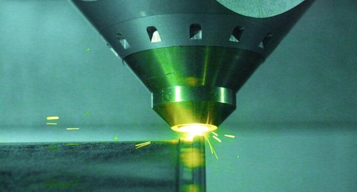
Another critical consideration is joining CFRPs to metals. Up to now, an adhesive bonding process has been used, which according to Tzanetos has four disadvantages:
The CFRP surface has to be machined mechanically. This leads to unsteadiness and a weakening of the CFRP’s properties.
It guarantees only a low level of mechanical strength (per joint: 10 to 40 megapascal).
It is closely dependent on the ambient conditions (e.g. temperature, soiling, chips, cooling lubricant).
Bonded joints possess a low resistance to wear.
Replacing steel: using CFRPs reduces the mass of the Z-axis by 60 per cent. Photo: MAP Werkzeugmaschinen GmbH
All these disadvantages are eliminated by a lasering process. But it’s not only the joining technology that MAP’s Branch Manager sees as problematic. “In order to assure precise positioning and reproducibility accuracies in the machine even in the case of high dynamic response, we scrape off the layers on the linear guides by hand,” says Tischmann. “It’s now an enormous challenge for us to accomplish this with CFRPs as well.”
Despite all these difficulties, the changeover to CFRP has been worth it, opines the expert with a view to EMO Hannover. The machine tool manufacturer is thinking about a shared information stand with the Fraunhofer IPT, in order to showcase the advances and procedures involved with this new material. “Basically, at the end of this project we aim to be putting a dynamic, high-precision, and above all powerful machine on the market,” explains Tischmann. “We would like to see it becoming widely accepted in the aerospace sector, particularly.”
EMO Hannover is also inspiring the academic community
The IPT scientist, too, sees collaborative projects like that with MAP Werkzeugmaschinen as a good option for exploring new paths in a process of mutual feedback with the industrial sector. The project currently ongoing has encouraged the researchers in Aachen to press ahead with industrial partners in the field of CFRPs. Tzanetos and his colleagues from the academic community will be getting further input on comparable materialrelated questions and on lightweight construction in September at the EMO Hannover.
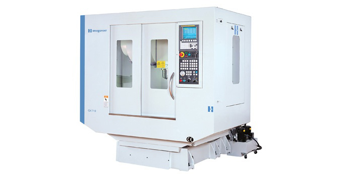
Thousands of GX-Series vertical machining centers are installed worldwide. These 40- 50 taper spindles VMCs include superior design characteristics to ensure many years of accurate and reliable performance.
GX-Series machines are ideal for mold and die manufacturers, aerospace, medical, defense, 3C, automotive and other industries, requiring high-value, complex parts from difficult to machine materials.
Superior design characteristics ensure Bridgeport 40-taper spindle GX-Series vertical machining centers deliver many years of accurate and reliable machining performance. These VMCs include a stiff and thermallystable spindle, a rigid C-frame fixed column design and fixed pre-tensioned double-nut ball screws on all axes. The unique Bridgeport-designed linear guide and guide truck configuration provides added stiffness, damping and surface contact area. The unit is configured with three guideways and five guide trucks on both the X- and Y axis, two guideways and six guide trucks on the Z-axis.
For more information, contact F&H Machine Tools – Tel: (011) 397 4050
The FANUC Roboshot has 9 models ranging from 15 ton to 300 ton and can be ordered with a wide range of screw diameters and injection speeds which can be selected to best suit your application.
The FANUC Roboshot utilizes the same highly reliable CNC technology that can be found in all FANUC products. As with all FANUC products, the Roboshot is backed by FANUC’s lifetime maintenance policy.
Precision molding repeatability is achieved through the low friction, highly rigid mechanism that utilizes FANUC Servo technology, thus making the machine fully electric driven. This also means that the machine is very economical to run as the servo system uses a regenerative function to conserve power.
Features
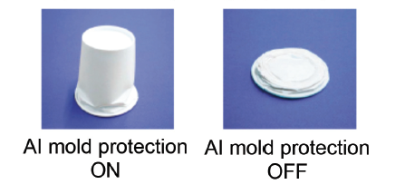
AI Mold Protection is a function designed to protect your mold by monitoring the torque of the servo motor during opening and closing motion of the mold. This allows obstructions to be detected before damage occurs.
Experimental example of AI mold protection by using paper cup
This function is also used on the ejector pins to monitor for abnormal ejector condition.
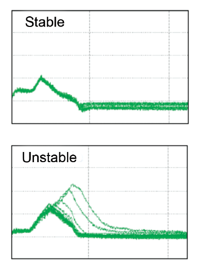
Backflow Monitor Function is used to monitor continuous production to check the stability of the molding process. Minor changes can be made to the settings on-the-fly to adjust stability and the results are displayed graphically on the backflow monitor screen.
Pre-Injection Function can be used to allow gasses to escape through the parting line before the mold fully closes. This allows for faster cycle times and better quality components as mold cavities will have less gas contamination.
The FANUC Roboshot comes standard with Euromap interface for easy connection to picker robots and can be easily connected to FANUC Robots. A hardware and software interface for connecting signal related equipment also comes as standard.
FANUC Roboshot-Linki is a software package that is separately available for the FANUC Roboshot. This allows the monitoring of multiple machines in an automated factory. This software also allows the user to check various statuses, power consumption and production volumes.
FANUC also offers a second injection unit on the 50 ton to 150 ton machines for two colour process molding. The SI-20iA unit fits on top of the FANUC Roboshot and the operation screen intergrates onto the Roboshot’s screen offering the same level of accuracy and repeatability.
FANUC Roboshot is made in Japan and comes with a 2 year mechanical and control warranty.
The FANUC Roboshot is available from FANUC South Africa.
For more information, contact FANUC South Africa – Tel: (011) 392 3910
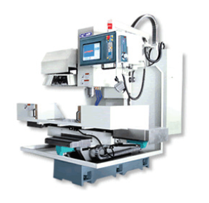
CNC machining is quicker and certainly more accurate than conventional milling machines and there is no need for constant monitoring while in use. Taking this into account, MJH Machine Tools have a solution to suit customers’ needs. Featuring an entry level CNC control, our Ctek CNC milling machine is the first step to CNC machining.
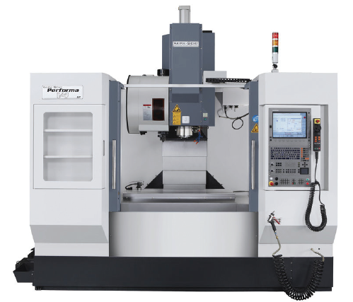
Akira Seiki Milling Machine
As long as the operator has basic knowledge on using a DRO, he can, within a few hours, be taught how to program and run the machine. There is no need for G code knowledge as the control is conversational, using a question and answer format. The software is simple to use with graphic input in basic machinist language. The control has options for standard operation modes such as drill, tap, bore, contour and pocket programming, which is ideally suited to general engineering work without a need for external programming packages.
The latest Ctek’s come with linear guides on all three axes for better accuracy and speed, as well as a direct spindle drive motor and an improved Z axis motor with inline break which eliminates the need for a counterbalance. The Ctek can be fitted with a 4th axis within a matter of hours and programmed from the standard Ctek control.
Ctek CNC Milling Machine
The Ctek range has six x-travel sizes, 800mm, 1000mm, 1500mm, 1800mm, 2000mm and 2500mm. These machines are available in open type or fully enclosed depending on the customer’s requirements. All spares are available ex stock at a fraction of the cost compared to other controls. With hundreds of these machines sold throughout South Africa since 1997, it is not surprising that Ctek CNC milling machines have been the first step to full CNC machining in many workshops.
Should there be a requirement for a high performance machining centre for super fine finishing and accuracy, the Akira Seiki is the machine to consider. Spindle power ranging from 15HP on the Junior series to 42HP on the Super Vertical range and spindle speeds from 9000rpm to 15000rpm guarantee high quality surface finish.
Akira Seiki machines come standard with spindle oil chillers, inner spindle air chiller, coolant through spindle, pneumatic counter balance, chip screw conveyor, quick change ATC and 4th axis preparation.
The Mitsubishi Mi745 is the preferred control on these machines, however, Fanuc is an option but not always available ex stock Durban or Johannesburg. So, whether you need a machine for small batch jobs or production work, the Ctek and Akira Seiki machines are certainly to be considered.
For more information, contact MJH Machine Tools – Durban Tel: (031) 705 7514 or Johannesburg Tel: (031) 705 7514
Over the years, Hurco’s entry-level machining centre, the vertical-spindle VM1, evolved into the more capable VM10 and the manufacturer has continued to improve the specification.
Linear travels have been extended, a larger toolchanger is provided, spindle speed and rapid traverse are both faster and a spindle chiller and throughspindle coolant have been added. This progressive upgrade has left room for a new entry-level CAT/BT40 machining centre, the VM5i.
A notable feature of the machine is its compact footprint, despite it having generous axis travels of 457mm, 356mm and 356mm in X, Y and Z. A VM5i can enter a factory through a door just 1.64 metres wide by two metres high and occupies a small space when it arrives.
High quality build includes a rigid cast structure, linear guideways in all axes and Yaskawa digital drives. The spindle is rated at 7.5 kW / 8,000 rpm and is supplied with cutters automatically from a 16-station magazine via a swing-arm tool changer.
Hurco’s proprietary Max5 control rounds off the package, providing industry-leading conversational programming capability. It features a 19-inch LCD display with touch-screen navigation and a keypad that is adjustable by up to 90 degrees.
Worthy of special mention is that Ultimotion forms part of the standard software bundle. It controls axis movements using an advanced algorithm, rather than relying on hardware-based motion control, minimizing the need to decelerate when the cutter changes direction. As a consequence, cycle times are said to be up to one-third faster. Additionally, chatter, vibration and jerk are lower, resulting in improved surface finish on machined components.
For more information, contact Hurco South Africa – Tel: (011) 849 5600.
Compact, highly dynamic, high-precision 5-axis HSC machine with counter bearing and special Röders geometry compensation.
The highest accuracy – well beyond what can be expected from comparable systems currently available on the market – is achieved by a number of features such as a sophisticated temperature management system, a spindle length deviation compensation device and an integrated tool-measuring system using a laser. A further feature in this context is a highly accurate contact-point measuring system for the workpiece.
For more information, contact Hurco South Africa – Tel: (011) 849 5600.
The DMU 50 combines more than 20 years of experience, proven technology and low investment costs in the 5-axis portfolio of DMG MORI.
On this basis and enhanced in all respects the bestseller has moved into the next round. This compact DMU 50 3rd generation sets new standards in 5-sided to 5-axis simultaneous machining. With its extended swivel range, more powerful spindle and its innovative cooling concept the world premiere guarantees a competitive edge in a multitude of branches. Its areas of application range from training, to general mechanical engineering, jig construction and on to include applications in demanding branches such as the aerospace, medical and automotive industries.
The 19″ DMG MORI SLIMline® Multi-Touch Control is one of a many Highlights of the new CLX 350.
While redeveloping the DMU 50 3rd Generation DMG MORI has managed to harmonize the modern appearance of the design with user-friendly operation. The large, smooth opening door to the work area, for example, with a width of 876mm ensures unrestricted access from the front, even in combination with automation solutions. The table also has an ergonomic loading height of 800mm. The optimum accessibility of the DMU 50 3rd Generation even encompasses maintenance components such as the control cabinet, fluid box, oil mist separator, heat exchanger and cooling unit.
Travel paths of 650 x 520 x 475mm and workpiece weights of up to 300kg mean the new DMU 50 3rd Generation covers a wide range of components. Its new NC swivelrotary table with an enlarged swivel range of −35°/+110° boosts this versatility. A rapid traverse of 42 m/min and 30 rpm in the swivel-rotary axis ensure the dynamics for 5-sided to 5-axis simultaneous machining. In addition to the 15,000 rpm speedMASTER® motor spindle, the user can also choose between motor spindles with up to a 20,000 rpm. Also available as an option is an expanded tool magazine with up to 120 pockets. There are 30 tool pockets in the standard version.
As basic universal turning center the CLX 350 realizes highly sophisticated machining operations in top quality.
The DMU 50 3rd Generation achieves a unique degree of precision of less than 6 μm that is unbeatable in this segment thanks to its one-piece machine bed on the one hand and on the other its innovative cooling of the guides, drives and table bearings. Directly driven ball screws and direct path measuring systems in all five axes round off the equipment with regard to the machine’s high degree of precision. The DMU 50 3rd Generation can be expanded with coolant tanks and tool measurement as an option.
A 21.5″ ERGOline® with CELOS® and Siemens 840D solutionline as well as a 19″ ERGOline® with HEIDENHAIN TNC 640 are available as modern control options. DMG MORI also has diverse automation solutions in its program for the DMU 50 3rd Generation, such as workpiece or pallet handling systems. This enables the world premiere to master challenging applications in the future-oriented aerospace, medical, automotive and energy branches – a demand that was already taken into account during the practice-oriented development of the machine. In other words, the DMU 50 3rd Generation continues to fulfil all the requirements that ensure it will remain DMG MORI’s bestselling 5-axis model.
Highlights of the DMU 50 3rd Generation include a 78 percent larger work area, 40 percent higher rapid traverse with speeds of 42 m/min as standard, 28 percent greater swivel range, a swivel rotary table with -35°/ +110° and 5-axis simultaneous machining as standard.
For more information, contact Retecon – Tel: (011) 976 8600.
“You can’t approach big parts the same way you would any other part, and that’s why everything about the a120nx is sized for heavy-duty manufacturing,” said John Einberger, product line manager at Makino. “We wanted to employ the proven designs of our other nx-series machines, such as three-point leveling and tiered column design, while ensuring that the machine could mechanically handle the unique challenges of large workpiece machining processes.”
The a120nx features vast X-, Y- and Z-axis travels of 1,900mm, 1,600mm and 1,700mm, respectively, and the machine’s standard large pallet size of 39.4 inches by 39.4 inches provides capacity for parts weighing up to 11,000 pounds. The machine’s automatic pallet changer switches from one pallet to the next in 38 seconds, minimizing non-cut times for the highest levels of productivity. Capable of storing up to 204 tools of wideranging sizes and designs, the a120nx accommodates tools up to 35.4 inches long, 14.0 inches in diameter, and weighing up to 77 pounds. Tools are loaded into the automatic tool changer (ATC) from an easily accessible, ergonomically friendly exterior loading station to prevent operator fatigue.
Built for Rigidity During Continuous Production
At the foundation of the machine is a threepoint supported bed casting to ensure all points are stable and contacting the floor. Developed to maintain the machine geometry and alignments, this design characteristic of the nx-series machines simplifies installation and enables easy relocation of the machine. Building on the rigidity of the bed casting, the a120nx uses a unique tiered column design that delivers greater resistance to Z-axis cutting forces throughout the work envelope. Robust cross roller-style B-axis table bearings work in concert with a high force rotary clamping system to ensure stable cutting throughout the machine’s expansive work zone.
The a120nx is equipped with Makino’s four cone pallet location and clamping system that delivers a secure 46,500 pounds of force on the pallet. This superior clamping capability, combined with all pallets built to a master pallet, eliminates deflection. An engineered precision air-blow system provides locating surfaces cleaning, as well as pallet clamp confirmation as standard features.
Larger parts typically mean larger features, too. Tool length, diameter and weight capacities of the a120nx support processes that feature the use of large face mills, boring bars and line-bar tooling.
To further ensure ideal geometry and accuracy, the a120nx has a number of systems in place to manage the heat generated by rapid traverse of 2,126 inches per minute. For one, the ballscrews are core-cooled in all axes to give consistent accuracy during continuous production. Moreover, the ballscrews are all dual supported and pre-tensioned to ensure unparalleled dynamic positioning repeatability. Feature-to-feature movement distances on large parts are typically much greater, so rapid traverse rates were increased for the a120nx in order to cover these expansive distances quickly.
Powerful Spindle, Pallet Clamping for Speed and Accuracy
Beyond its proven speed and accuracy, the a120nx also improves productivity in cutting and non-cutting performance. The standard high torque 8,000-rpm spindle boosts continuous power levels by 19 percent over levels typical to machines of this class. With 50 continuous (74 peak) horsepower available, this spindle is ideally suited for heavy roughing of iron castings and hard-metal applications. In addition, the spindle features significant improvements in acceleration and deceleration due to its high duty rated performance characteristics that reduce rigid tapping times by up to 30 percent. Also available is an optional 18,000-rpm high power spindle, ideally suited to high metal removal rate machining of light alloy structural components.
Chip and coolant management features are often overlooked and result in interrupted operations, increased labor costs, machine damage, part-quality issues and reduced tool life. The a120nx enables shop owners to avoid these challenges with supplementary management features, including a sloped surface to remove obstacles between the workpiece and an external chip conveyor, letting chips fall freely. The trough design facilitates rapid chip and coolant evacuation and reduces maintenance needs with a solid panel Z-axis cover design. A standard cyclonic filter provides ultra clean coolant to the through spindle coolant pump and acts as a secondary coolant filter, polishing coolant in the main tank.
The a120nx comes to the market automation ready, being fully compatible with Makino’s versatile multi-machine, multi-pallet MMC2 flexible manufacturing system, complete with Makino’s highly capable MAS-A5 cell controller. Machining massive parts poses multiple challenges. However, speed, accuracy and durability remain crucial when working with large parts and meeting customers’ delivery demands.
For more information, contact Rothco – Tel: (011) 970 1930.




 Pre-Injection Function can be used to allow gasses to escape through the parting line before the mold fully closes. This allows for faster cycle times and better quality components as mold cavities will have less gas contamination.
 FANUC Roboshot-Linki is a software package that is separately available for the FANUC Roboshot. This allows the monitoring of multiple machines in an automated factory. This software also allows the user to check various statuses, power consumption and production volumes.


 Compact, highly dynamic, high-precision 5-axis HSC machine with counter bearing and special Röders geometry compensation.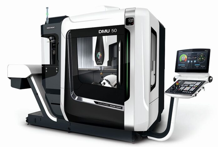


 To further ensure ideal geometry and accuracy, the a120nx has a number of systems in place to manage the heat generated by rapid traverse of 2,126 inches per minute. For one, the ballscrews are core-cooled in all axes to give consistent accuracy during continuous production. Moreover, the ballscrews are all dual supported and pre-tensioned to ensure unparalleled dynamic positioning repeatability. Feature-to-feature movement distances on large parts are typically much greater, so rapid traverse rates were increased for the a120nx in order to cover these expansive distances quickly.
 Chip and coolant management features are often overlooked and result in interrupted operations, increased labor costs, machine damage, part-quality issues and reduced tool life. The a120nx enables shop owners to avoid these challenges with supplementary management features, including a sloped surface to remove obstacles between the workpiece and an external chip conveyor, letting chips fall freely. The trough design facilitates rapid chip and coolant evacuation and reduces maintenance needs with a solid panel Z-axis cover design. A standard cyclonic filter provides ultra clean coolant to the through spindle coolant pump and acts as a secondary coolant filter, polishing coolant in the main tank.