Home Blog Page 2

NEW BRAKE DISKS PRODUCE SIGNIFICANTLY LESS FINE DUST


Innovative coating makes the brake disks fit for strict Euro 7 standard


Jannik Röttger can still remember the first attempt at grinding a hard-coated brake disk: “The grinding disk broke in the machine”, he adds. The new, extremely hard material was considered revolutionary in the industry. Röttger is now Head of Grinding Technology at the machine tool manufacturer Emag in Salach, Baden-Württemberg. And the brake disks, which were tested at that time in the machine tool laboratory of RWTH Aachen, are close to a major breakthrough. They meet the strict requirements of the Euro7 standard and from 2026 should ensure that the hazardous fine dust pollution in traffic areas is reduced considerably. Approximately 100 million brake disks are produced in Europe every year.

Up to 90 percent less fine dust when braking

The development of the brake disk, with which the arising particle quantities during braking can be reduced by up to 90 percent, was a major accomplishment for the industry. A hard coating was preferred early on because it was considered particularly efficient, corrosion-resistant and durable. One flaw: its price. Fans of sports cars and SUVs in the luxury class might be prepared to pay up to five-figures for a particularly efficient brake system. But this does not hold true for the majority of motorists. An affordable variant had to be found.

The Fraunhofer IKTS (Institute for Ceramic Technologies and Systems) in Dresden, among others, focused on the development. As stated, for the new coating a powder of carbide, a mixture of carbon and a metal, is mixed using a special nozzle system and applied to the rotating brake disk with a laser. This method and the powder materials used allow very thin layer thicknesses to be achieved. It is essential that the expensive material carbide is used very sparingly. The subsequent grinding process is about achieving the required surface properties.

Digital networking is a must

Suitable machine and tool technology is now available, corresponding production lines are entering the halls of the automotive industry. Comprehensive test runs, during which thousands of brake disks were machined, led to the desired results. But that alone was not enough. For economic production, optimization potential across all technologies was sought in the entire manufacturing process from the casting of the blank, to turning, laser coating and grinding through to the resulting function properties in the vehicle. Attention was also paid to how the manufacturing process can be modified in a targeted manner and customized depending on the raw material and individual requirements. What’s more: “Already in the early phase of the development our customers wanted to have everything documented”, reports Mario Preis, Head of Technology & Corporate Development at DVS Technology Group, Dietzenbach, who specializes in surface treatment. The brake disk is always a safety-critical component subject to high quality requirements. The companies are also required to document everything with regard to the EU CSRD (Corporate Sustainability Reporting Directive) on comprehensive sustainability reporting. For Mario Preis, there is no alternative to digital networking of the process chain. Only digital networking enables the system view to repeatedly adapt manufacturing processes to new requirements and to comply with documentation duties reliably and at the same time economically.

Service as a new business model

In order to facilitate entry into data-driven production, many machine tools are already equipped with extensive sensor and monitoring systems ex works. The machine builders also provide suitable infrastructure and software components so that data can be captured, analysed, and visualized across the entire process chain using different technologies. The VDW (Verein Deutscher Werkzeugmaschinenfabriken) in Frankfurt/Main wants to show how this works at its trade fair EMO Hanover, which takes place from 22 – 26 September. There the interest groups of machine tool manufacturers will bring together companies from almost all continents and present worldwide innovations in the area of production. And it is no longer just about innovative machines.

Emag, for example, will also present their solutions in North Germany. Because Jannik Röttger is convinced that competency in complex production contexts will be increasingly decisive for industry. “The process chain will become the business model”, he says, as is reflected using the example of the hard-coated brake disk. However, he still believes real tests cannot be completely eliminated in the digital world. At Emag at least they will be included once again for hard-coated brake disks – this time for commercial and rail vehicles.

MACHINES WILL THINK ALONG WITH US IN THE FUTURE


How artificial intelligence is revolutionizing production


Industrial manufacturing is undergoing a change for the ages. Artificial intelligence (AI) is finding its way into machine tools and is not only changing production processes, but also the maintenance of machines. AI is becoming the control centre for efficient, sustainable and competitive production. In times of skills shortages and international competitive pressure, it is far more than just a technological gimmick: it is becoming a survival strategy. At the EMO Hannover 2025, the world’s leading trade fair for production technology, you will be able to see how artificial intelligence is revolutionizing industrial production from September 22 to 26.

AI in machine tools means much more than just automation. It enables machines to learn from data, make decisions and optimize processes. Sensor technology, data analysis, machine learning and intelligent assistance systems are used for this purpose – both at the control level and in interaction with people.

Increasing the individual potential of AI

Prof. Philipp Klimant Fraunhofer Institute for Machine Tools and Forming Technology (IWU).

There are many possible applications for manufacturing companies: “Typical examples would be the prediction of process properties in real-time operation for inline quality control and the monitoring of processes and their properties,” says Prof. Philipp Klimant, Head of Business Unit Process Digitization and Manufacturing Automation at the Fraunhofer Institute for Machine Tools and Forming Technology (IWU) in Chemnitz. “The advantage over traditional approaches is the ability to include a particularly large number of parameters in the monitoring process,” highlights Klimant.

However, there are also numerous other fields of application, such as AI assistance models for training and artificial intelligence to support maintenance. The Fraunhofer IWU, which specializes in the production-related adaptations of traditional and modern machine learning methods, is headed by the trio of Martin Dix, Welf-Guntram Drossel and Steffen Ihlenfeldt. All three are members of the WGP (Wissenschaftliche Gesellschaft für Produktionstechnik/German Academic Association for Production Technology), an association of leading German professors in the field of production science. As of January, the WGP has consolidated the ProKI initiative, which was originally funded by the BMBF, under its umbrella and has since been offering highly practical expertise and demonstrators, especially to small and medium-sized companies that want to find out about the potential of AI for their individual situation and/or are looking for support.

Great leverage for efficiency gains

The IWU researcher’s tip is to ask the following question at the very beginning: How large are the efficiency gains that are actually possible through AI in my production process? “The question of what efficiency gains are possible cannot be answered universally without further analysis,” says Klimant. The potential is heavily dependent on the actual process and the associated optimization possibilities. “In the field of plastics processing, injection moulding for example, reject rates of 20 to 30 percent can occur in rare cases.” This represents a major lever for efficiency gains with AI. It can also be useful for processes that are already running with a high level of stability, for example in the area of predictive maintenance and to achieve longer service lives of tools.

According to Klimant, artificial intelligence can also make an important contribution to alleviating the shortage of skilled workers. “We store knowledge implicitly in AI. This knowledge can be used to train new employees, especially when older colleagues retire and important knowledge leaves the company,” explains the scientist, who has also been Professor of Virtual Technologies at Mittweida University of Applied Sciences in Saxony since 2023. “This repository of AI knowledge also offers new opportunities for automation, not least for automated quality control,” says Klimant.

The researcher defines artificial intelligence as follows: “When we talk about AI, we usually mean machine learning as a subgroup of AI. This is able to learn independently from training data. It is an empirical process that learns correlations without us knowing the analytical correlations. Simply put, we learn from experience.” AI is used to optimize the process parameters in production and feed them back into the process controller via an automated control system. “Artificial intelligence is like a black box, input values go in and forecasts come out,” says Klimant. “One example of this would be a forming process where we measure an acoustic signal and then the AI tells us whether or not the process was successful.” Ultimately, it is a digital system that can be connected to control systems via existing interfaces. This allows AI to influence control algorithms at various points.

High computing power for image processing

In order for artificial intelligence to be used successfully in production, hardware with very high computing power is sometimes required. “First of all, a distinction must be made between the training phase and the utilization phase (inference). The training phase is always more computationally intensive, but is carried out offline. In the utilization phase, edge devices are often sufficient for classic methods such as the support vector machine,” says Klimant. The situation is different when it comes to the topic of image processing. These AI models require more computing power, both in the training phase and in the utilization phase. “The application cycle also plays a decisive role here,” explains the researcher. “If I need a result every five seconds, for example, I will need more computing power compared to a cycle time of 30 seconds.” The evaluation of language models represents an exception here. These require powerful hardware, from high-performance consumer graphics cards through to special AI cards.

Self-learning machine tools enabling autonomous production

Jonas Gillmann, Chief Technology Officer (CTO).

Self-learning machine tools are made possible by AI. Milling machine manufacturer and EMO exhibitor Datron AG from Ober-Ramstadt near Darmstadt makes use of this innovation, in which the machine draws on learned knowledge and adapts the production process. The aim is to develop Datron milling machines into adaptive production cells that automatically adjust to component requirements and environmental conditions. “This not only reduces set-up and machining times, but also increases process stability – a decisive step towards autonomous production,” says Jonas Gillmann, Chief Technology Officer (CTO) of the publicly listed mechanical engineering company.

AI is thus shifting the focus away from rigid programming towards assisted, self-learning and adaptive production. “Machines are becoming partners in the manufacturing process, which adapt to humans – not the other way around. In mechanical engineering, this is no longer a vision, but is increasingly becoming a reality,” says Gillmann. As he explains, AI in production offers high levels of efficiency gains: “In CNC production with Datron machines, it can reduce set-up times by up to 60 percent, significantly reduce the amount of rejects and extend the service life of tools – while at the same time increasing process reliability.”

Intuitive guidance through the milling process

One particularly exciting advance is the link with the “Datron next” control software, says Gillmann. This guides even inexperienced operators intuitively through the milling process and automatically recognizes workpieces. “This means that even employees who are not specialized in the technology can perform milling productively – a clear advantage in view of the shortage of skilled workers,” says the Datron Chief Technology Officer, who started his career as an industrial mechatronics technician at the milling machine manufacturer from Hesse. According to Gillmann, AI will in future also allow predictive maintenance to be carried out in order to prevent failures before they occur. “This will make the milling process more efficient, more robust and much more flexible in terms of the personnel required.”

Artificial intelligence in machine tools can also help to meet the increasing demand for customer-specific products with small batch sizes. “AI makes the production of small batch sizes economical: With the Datron next control software, workpieces are recognized automatically – without complex programming,” says Gillmann. “This eliminates the need for long set-up times, and individual parts can also be manufactured quickly, efficiently and to a high level of quality – which is ideal for customized products.”

Less programming, more process responsibility

Self-learning machine tools are also changing the job description of the user: “Less programming, more process responsibility,” is how the Datron CTO sums up the change. Employees are becoming process designers who ensure quality and optimize processes. “This lowers the barrier to entry and human expertise is supplemented – not replaced – by smart assistance.”

50 YEARS OF EMO – PEOPLE, MACHINES, MILESTONES

Industry 4.0 under its own control: Maschinenfabrik Heller has been implementing the EMO 2017 motto "Connecting systems for intelligent production" with its own networked production lines for years.

By Nikolaus Fecht, Gelsenkirchen, Germany

In June 1975, almost all of Paris is dreaming of love – à l’électronique. As the new, electronically controlled RER high-speed train begins its journey, the Centre Pompidou with color-coded pipes and electronic building technology is being built in the middle of the city. At the same time, the international machine tool industry celebrates the premiere of the “Exposition Mondiale de la Machine-Outil” – EMO for short – at the Parc des Expositions de la Porte de Versailles. The common denominator of the three events is that they herald the global dawn of a new era in which electronics are gradually taking over. A look back by technology journalist and contemporary witness Nikolaus Fecht.

Farewell, EWA – that’s the word in Paris in 1975 and two years later in Hanover. EMO is the successor to the “European Machine Tool Exhibition”, which has been held alternately in Belgium, Italy, France and Germany since 1951. The continental industry show will become an international event, to which the European machine tool association Cecimo invites visitors alternately to Milan, Paris and Hanover.

Numerical control: cam disk and camshaft passé

For the first time, the European machine tool industry will be showcasing itself at a trade fair with international appeal throughout. One impulse from the USA in particular caused a stir in the mid-1970s: numerical control (NC). Cam disks, camshafts and mechanical copying devices have been replaced by programmable control systems that allow motion sequences to be flexibly defined via software for the first time. But this is just the beginning, oracles a German trade journal at the time: “The first machine tool world congress concludes with a discussion on the future development of machine tool control in conjunction with the use of computers.” But it’s not that far yet, punched tape still dominates the scene – the classic storage medium for numerically controlled machines.

German EMO premiere – In 1977 – two years after Paris – the machine tool industry showcases itself for the first time on a global scale in Hanover.
Nikolaus Fecht

I learned about the next step towards CNC – “Computerized Numerical Control” – as a working student in the mid-1970s in Thyssen’s large training workshop in Kassel. However, the handling of this technology needs to be learned first: “Hands off, this is not for beginners!” a master craftsman tells the budding electrical engineer as he curiously inspects his first CNC machine: A CNC machine tool over three meters high – equipped with an early Siemens control system. The student looks at a magnetic tape input system that glows amber.

Advance from Japan – Every fourth lathe has a CNC system

No wonder I’m fascinated by the newcomer – after all, CNC is still a technical exception in the mid-1970s. According to the National Bureau of Economic Research, Cambridge (USA), less than five percent of machines in the United States are CNC-controlled, and only around two percent in the Federal Republic of Germany. Only Japan is much further ahead: In 1975, one in four lathes exported already had a CNC system – and the trend is rising sharply.

The production experts look with enthusiasm at computer solutions from the Far East or the USA, but for a long time they are sceptical: I am one of them. During my first visit to EMO in Milan in 1987, as a trade editor I get to know high-tech from the Far East: Mitsubishi presents a CNC system that supposedly works five times faster than conventional 16-bit systems and even optimizes machining automatically thanks to artificial intelligence. For me as an engineer journalist, a new era is beginning, which I refer to in the trade press as “CIMsalabim” – a tongue-in-cheek allusion to “Computer Integrated Manufacturing” (CIM), where robots, machine tools, assembly lines, measuring stations and computers merge to form a computer-integrated factory.

The digital trend will soon be followed by green issues – initially ridiculed, then promoted and finally demanded. High-speed machining (HSC) played a key role. The process enables extremely fast machining with high surface quality – and with very little or no cooling lubricants. At EMO Hanover 2001, Getrag Ford Transmission GmbH demonstrates how HSC and minimum quantity lubrication can be combined to conserve resources. During an on-site report for the EMO press service, I learn: “One glass of Kölsch beer is enough to process 90 gearbox housings” – previously it was 220 litres of emulsion. The VDW also recognizes the potential early on. HSC became a promoted key technology, flanked by eco projects and the Blue Competence initiative. At EMO 2011 at the latest, it becomes clear that energy efficiency is no longer a sideshow.

Dry machining with HSC: High-speed machining entirely without cooling lubricant – what started out as an experiment at the beginning of the 21st century has become a symbol of resource-saving manufacturing.

Industry 4.0 – from label to evolution

A few years later, a new guiding principle provides further impetus: Industry 4.0 stands for the idea of networking production systems using powerful computers, sensors and interfaces in such a way that they can be controlled and analysed in real time – ideally even by cell phone. “A smartphone for production”, a developer says in a tongue-in-cheek manner at EMO Hanover in 2017.

However, the first step is to link systems intelligently with one another. Under the guiding theme of “Connecting systems for intelligent production”, EMO is sending out a clear signal for digital networking in production technology. In 2019, umati (universal machine technology interface) – the global initiative for open communication interfaces for the mechanical engineering industry and its customers based on OPC UA information models, initiated by the VDW – celebrates its premiere in Hanover. Since then, umati has continued to develop: Today, under the umbrella of VDW and VDMA, the international community guarantees standardized information models for numerous applications, offers a platform for exchanging experiences, creates visibility on the market and enables the practical demonstration of added value. Open interfaces now exist not only for machine tools, but also for components, software solutions and many other manufacturing technologies – a decisive contribution to the smooth cooperation of a wide variety of systems in networked manufacturing.

The year 2020 becomes a test: Within a short space of time, virtual communication becomes established – a replacement for coronavirus-related contact restrictions. Companies are switching to remote maintenance, digital customer formats and flexible logistics. Further adjustments follow in 2022 with the loss of Russian gas supplies – from energy efficiency to the realignment of global supply chains. Industry 4.0 is becoming a living practice. Virtual services such as remote maintenance, remote diagnostics and online training are replacing on-site deployment in many places. Digital tools support customer contact, while cloud-based platforms enable training and support regardless of time and place.

Industry 4.0 under its own control: Maschinenfabrik Heller has been implementing the EMO 2017 motto “Connecting systems for intelligent production” with its own networked production lines for years.

Efficient communication despite coronavirus contact restrictions

Contactless communication works efficiently, I observe while researching for a text: “Digitalization shows its strength above all in combination with online communication. We are talking about troubleshooting, teleservice and remote diagnostics, the flexibility of which many companies have come to appreciate in times of crisis.” The pandemic is therefore becoming a catalyst for digitalization – in service and in interaction. This experience still shapes our service structures today. Some people wonder whether physical trade fairs are still necessary at all – after all, virtual communication works surprisingly well these days.

Virtual communication is here to stay – but the next technological leap is already in the pipeline. Shortly after the digitalization push caused by the pandemic, an old acquaintance is back in the spotlight: artificial intelligence. While Asia and America are already investing, Professor Jörg Krüger from the Fraunhofer Institute for Production Systems and Design Technology IPK, Berlin, warns: “Without AI, soon a knockout (KO)” – and advises linking the domain knowledge of workers with neural networks. Data is the “digital gold dust” of production, from which new business models can emerge. This claim will become tangible at EMO 2023: Trumpf presents an AI assistance system for the automatic sorting of sheet metal parts, J.G. Weisser shows predictive maintenance based on learning algorithms. Mapal, Ceratizit and the Fraunhofer IPT also demonstrate how AI optimizes manufacturing processes, reduces testing times and makes machines more intelligent. AI is on its way from buzzword to standard – visible at more and more stands at EMO.

And yet EMO 2023 in particular showed that networking does not replace personal exchange, but enriches it. Under the claim “Innovate Manufacturing.”, the VDW attracted over 90,000 experts from all over the world to Hanover – around half of them from abroad. The trade fair impressively demonstrated that digitalization promotes dialog. In Hanover, I have come full circle, having stood at my first CNC machine 50 years ago as a curious student worker – and now reviewing half a century of EMO experience as a technology reporter. My exciting question: What happens next?

My research shows that EMO 2025 will once again focus on digitalization, automation and sustainability – complemented by new AI applications. Together with Siemens, DMG MORI is showcasing an end-to-end digital twin. Sandvik Coromant launches smart tool holders with real-time monitoring. Supfina presents a new machine concept for surface finishing, and VibroCut introduces ultrasonic support for machining. At the same time, MAPAL reminds us that classic tool solutions still have their place. VDW Chairman Franz-Xaver Bernhard puts it in a nutshell: “The future of production is created where innovation meets experience – and that is precisely the strength of EMO.”

CUTTING DATA AND CUTTING CONDITIONS


“It is a capital mistake to theorize before one has data.” – Sherlock Holmes


Generally, cutting data relates to quantitative variables that determine running a cutting process numerically. Cutting data can also be referred to as cutting parameters. Cutting data consists of cutting speed, feed, depth of cut, width of cut, machining allowance (stock), number of passes and tool overhang plus additional parameters that depend on specific features of a particular machiningoperation. For example, these parameters include the spindle speed that characterizes a rotating workpiece or tool in cutting with rotational primary motion, step-over and step-down, which define a tool displacement in radial and axial directions after every pass in milling. Even though cutting data is often identified with cutting conditions, its actual value is questionable. Cutting conditions typically include machining factors that are difficult to quantify. For instance, unfavourable cutting conditions relate to a whole set of reasons, such as workpiece with skin (siliceous or slag, for example), significantly variable machining allowance that leads to changing the depth of cut, considerable impact load, due to non-uniform machined surface and surface with high abrasive inclusions.

In another case, unstable cutting conditions refer to the low stability of a complete machining system, including machine tool, workpiece holding fixture, cutting tool and workpiece, due to poor tool and workpiece holding, high tool overhang, non-rigid machine tools and thin-walled workpiece.

Principally, the terms “unfavourable” and “unstable” cutting conditions are not interchangeable. However, despite their differences in definition, these conditions are related through cause and effect and are sometimes used as synonyms in certain contexts.

In characterizing cutting conditions, the terms “heavy” and “heavyduty” machining are often used improperly. Moreover, these terms are sometimes mistakenly regarded as synonyms. In principle, “heavy machining” refers to machining large-sized and heavyweight workpieces on powerful machine tools, primarily relating to the dimensions and mass of the workpiece. In contrast, “heavy-duty” specifies a degree of tool loading and mainly characterizes a mode of machining.

A “Golden Rule” for manufacturing engineers, process planners and machinists states: “Avoid heavy-duty machining under unfavourable conditions, especially if your technological system is unstable!

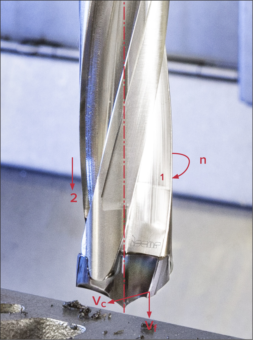
To summarize, a general description of cutting conditions depends on various aspects that are difficult to define. In many cases, finding cutting data for a specific machining operation is relied upon the user’s estimation of cutting conditions related to light, normal and hard. In primary motion, the points of a tool cutting edge move with appropriate velocities. The maximum velocity is the cutting speed vc. For example, in drilling a hole by a drill rotating with rotation velocity n, the cutting speed is the circumferential velocity of the point farthest from the drill axis. In fact, the cutting speed is the relative linear speed between the cutting tool and the machined surface of a workpiece. For a rotary body of diameter R, the circumferential velocity v is defined by the following equation:

v=ω×R                     (1)

ω – angular velocity in radians per second (s-1)

In machining, rotation velocity in revolutions per minute (RPM, rpm) is used instead of angular velocity in radian per second. The cutting speed is measured in meters per minute (m/min) in metric units and surface feet per minute (SFM, sfm) in US customary and imperial systems.

vc can be calculated as below:

vc=π×d×n/1000 m/min                     (2a)

and vc=π×d×n/12≈ d×n/3.82 sfm     (2b)

d is the diameter of a rotating tool in milling, drilling etc. or workpiece in turning that is expressed in mm in equation (2a) and in inches in equation (2b). Because both the rotating tool and the workpiece are mounted on a machine tool spindle – a part intended to transmit torque – rotation velocity n is often referred to as spindle speed.

Another velocity – feed speed vf – determines a feed motion. In fact, this is the speed at which the tool advances into the workpiece. There is a difference between feed speed and feed. The feed f is determined by the distance, which the point of a cutting edge travels along its path in the feed motion, to the appropriate number of cycles of another cutting motion. One revolution of a tool in milling or a workpiece in turning stroke in shaping – these are the examples of such a cycle. In the above case of drilling, the cycle is one revolution of a drill.

In North American countries the term “feed rate” is often used instead of the ISO definition “feed speed”. The less common term “advance” is a synonym for “feed”, like “advance per tooth” and “advance per minute” mean the same as “feed per tooth” and “feed speed”. Manufacturers can refer to “feed speed” as “table feed”. The original term refers to a classical machine, especially from previous generations, where feed motion was created by movements of the machine table.

In milling, the term “chip load” is commonly considered as a synonym for the term “feed per tooth”. This term is also more typical for the North American market. However, the correct synonym for “chip load” is “chip thickness”. In shop talk “chip load” relates usually to maximum chip thickness.

If the feed corresponds to one revolution of a tool or a workpiece, it is known as feed per revolution and designated also as f or, more rarely, fr. Feed per revolution is a common characteristic for machining processes like turning, drilling, countersinking etc.

In processes like shaping, planing and slotting, feed motion features double strokes that comprise forward (cutting) and backward (return) strokes. These processes are specified by feed per double stroke (sometimes simply feed per stroke if word “double” is omitted) fs. In many cases, however, feed per double stroke is denoted also by f.

In multi-point (multi-edge) cutting tools having teeth or flutes, feed per tooth fz is used. This is the feed that corresponds to rotation by one angular pitch of the tool teeth (flutes).

It is easily seen that:

f=fz×z                      (3)

where z is the number of tool teeth (flutes)

Further to this:

vf=f×n                       (4)

and

vf=fz×z×n                 (5)

Example: An ISCAR’s BAYO-T-REAM high-speed reamer carrying exchangeable eight-flute solid carbide head RM-BN9-32.000-H7LB is applied to reaming a through hole Ø32H7 mm (Ø1.2500H7) in a steel workpiece, which has a hardness value of HRC 51…53. ISCAR, as the reamer manufacturer, recommends the following initial cutting data: vc=40 m/min (131 sfm), fz=0.1 mm/tooth (.004 ipt). Find spindle speed and feed speed.

Metric system: From equations (2a) and (5)

n=1000×vc/(π /d)= 1000×40/(π /32) =398 (rpm)

vf=fz×z×n = 0.1×8×398=318.4 (mm/min)

US customary (imperial) system: From equations (2b) and (5)

n=12×vc/(π /d)= 12×131/(π /1.25)=400 (rpm)

vf=fz×z×n= 0.004×8×400=12.8 (ipt)

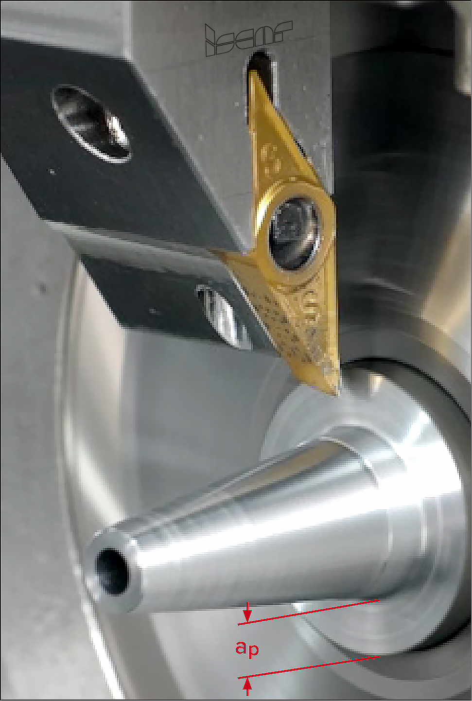
Depth of cut ap, one more cutting data parameter, is the distance between machined and unmachined surfaces of a workpiece. This distance is measured towards a normal to the machined surface. Practically, this is the distance that the cutting edge extends into the workpiece material. Depth of cut is often referred to as abbreviature DOC.

If D and D1 are diameters of machined and un-machined surfaces accordingly, ap in external longitudinal turning can be determined as below:

ap= (D1-D)/2         (6a)

In boring (internal turning), the diameter of a machined hole greater than the diameter of an un-machined hole and the previous equation takes the following form:

ap= (D-D1)/2         (6b)

In parting, the depth of cut is the same as the cutting-edge width. In grooving, the depth of cut corresponds to the width of the slot, performed by the grooving tool in one pass. If the groove width is equal to the width of a tool cutting edge and the groove is generated by one pass only, the depth of cut, is the cutting edge width.

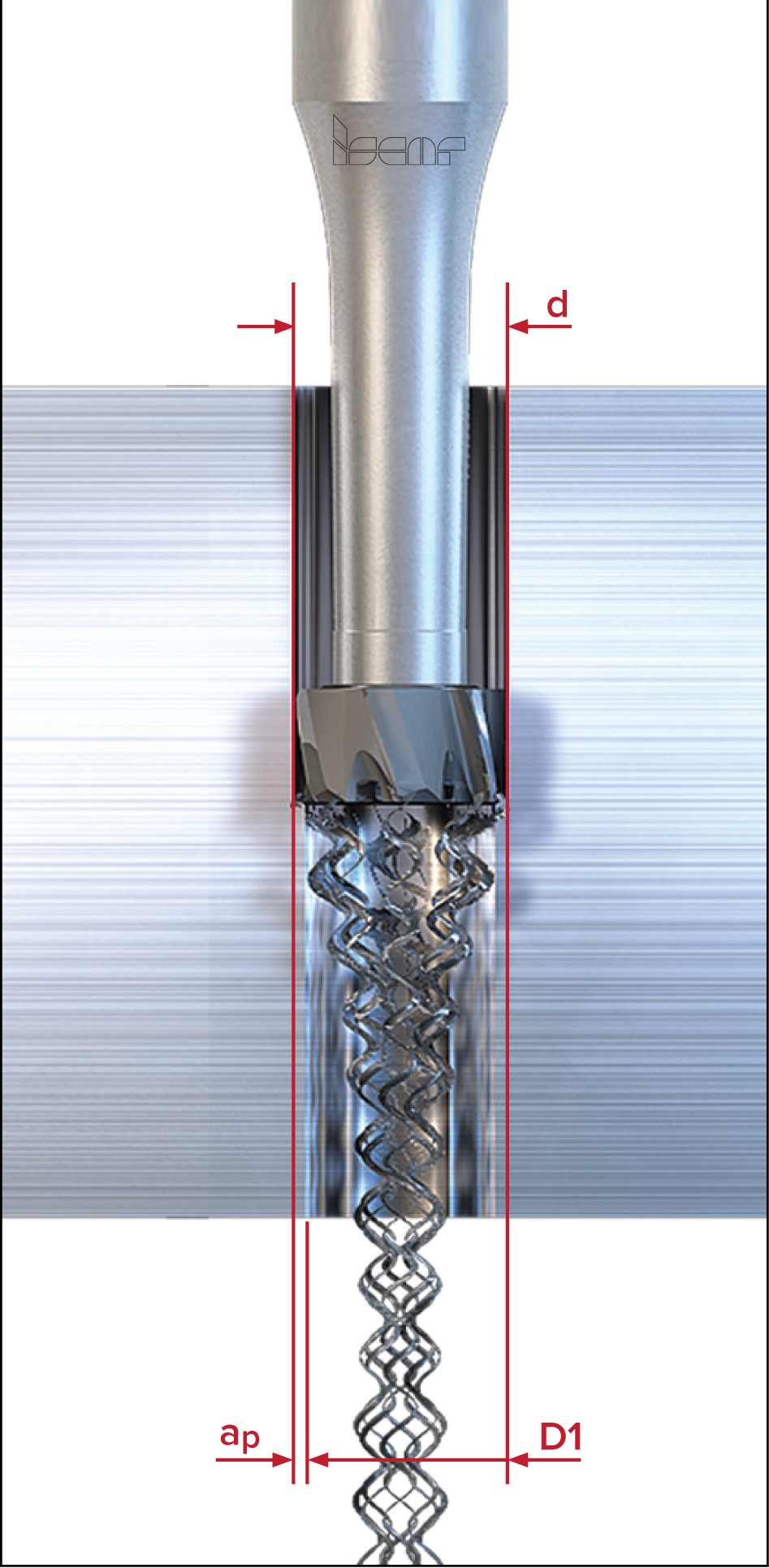
In counter-boring and reaming, the depth of cut is calculated using the following equation:

ap= (d-D1)/2           (6c)

d is the tool diameter

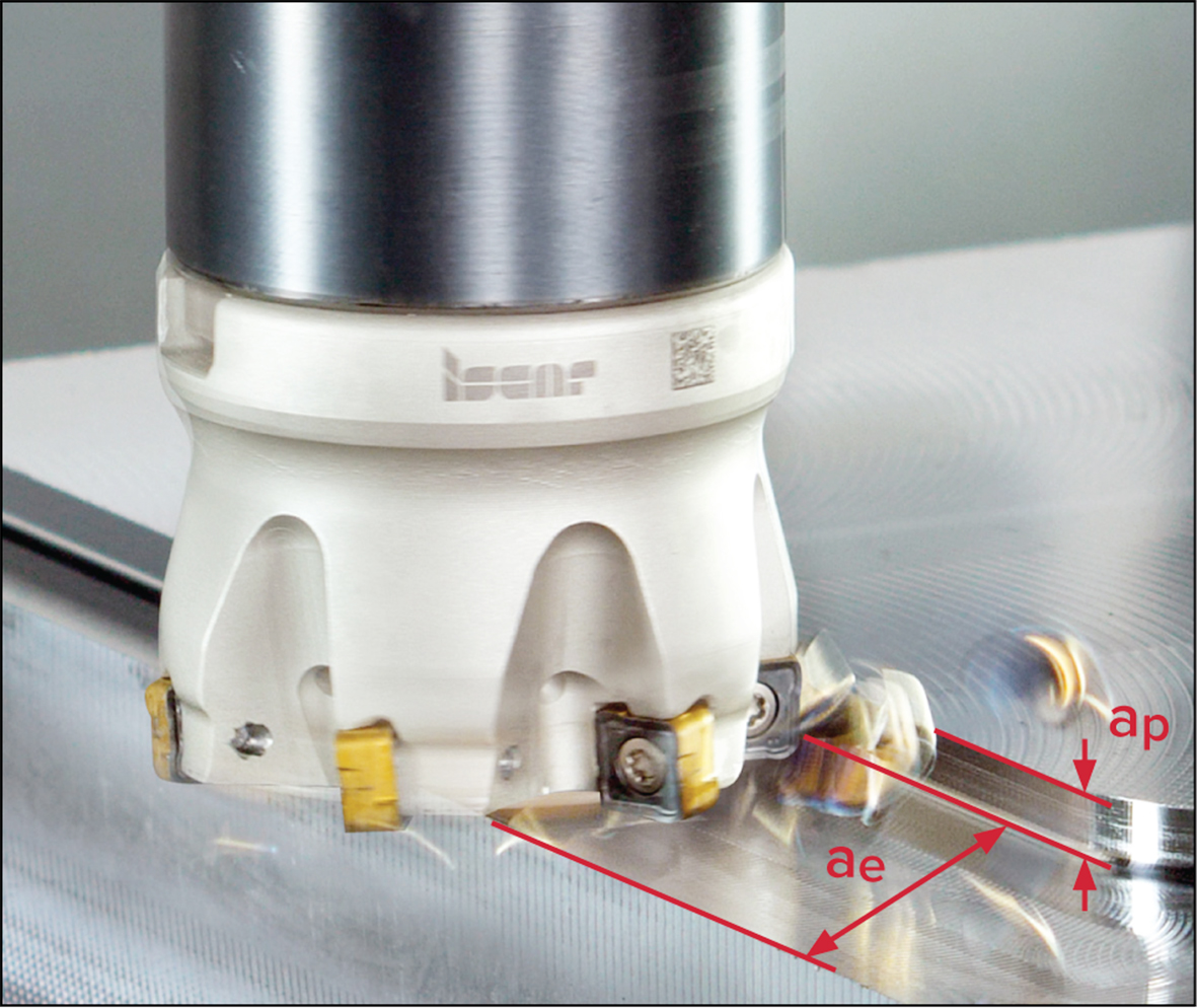
A typical milling cutter removes material with two of its surfaces at once, the periphery and the face. Therefore, in milling, the depth of cut relates to two process parameters that are measured in two different directions, such as axial depth of cut ap that is measured along the mill axis and radial depth of cut ae, which is measured radially when milling faces, shoulders and slots. The radial depth of cut is more known as width of cut – the width of a material layer that is removed by a mill in one pass.

Machining allowance, also known as machining stock or stock allowance, refers to the thickness of the material layer that should be removed during machining. There are two types of allowances, total allowance and process allowance. While the process allowance specifies the allowance for a particular machining process such as turning, milling, etc., the total allowance refers to all the material removed throughout the entire production of a part. The total allowance includes the allowances for all machining processes required in part manufacturing. Process allowance can be further divided into allowances for specific process operations, for example, rough turning, semi-finish turning and finish turning. These operations may be performed using a single tool or multiple different tools.

Machining allowance refers to the specific amount of material left for a cutting tool to remove in an application. Depending on the requirements for accuracy and surface finish, as well as possible tool limitations, like if the maximum depth of cut the tool can provide is less than the allowance, material removal can be performed with either a single tool pass or multiple passes. When defining cutting data for machining a workpiece made from a specific material on a particular machine, the following principles should be followed: In rough machining, the cutting depth is set to the largest possible value, preferably equal to the operation allowance or the greater part of it. The same approach applies to specifying the feed rate, it should be as high as possible within the constraints of existing technological limitations, such as machine power, cutting conditions, tool strength, etc.

In finish machining, the key factors for determining depths of cut and feeds are the required parameters of accuracy and surface finish, as well as the surface quality provided by the previous operation. Cutting speed depends on the characteristics of the tool and cutting material, cutting conditions, type of machining and prescribed tool life. The evolution of precise metal shaping techniques, such as precision investment casting, precision forging and 3D printing, are all capable of shaping a part very close to its final profile, significantly diminishing traditional chip-removal processes. As a result, the requirements for machining operations in engineering processes are changing. The role of productive and accurate cutting with small allowances at high speeds and feeds is expected to grow substantially, and metalworking industries will require a wider range of tools that are more precise and durable.

For more information, please contact ISCAR South Africa (PTY) LTD – Tel: 011 997 2700.

Visit ISCAR

REIME NORIS – PRODUCT RANGE FOR UNIVERSAL THREAD MILLING CUTTERS EXPANDED

As an innovative manufacturer of threading tools, REIME NORIS offers an extensive range of products for the economic production of threads in a wide variety of materials. The company is now expanding its successful thread mill series NORIS SF R15. In addition to the thread types M, MF and G, this tool is now offered for the production of UNC and UNF threads.

The NORIS SF R15 is a multi-row thread mill for processing a wide range of materials. It guarantees short machining times and high tool life. It should be particularly highlighted that the thread is efficiently produced over the entire depth of the core hole with only one turn, for the type SF SE even with countersinking. With a helix angle of 15° right, these thread mills can withstand high mechanical stress. Optimum results are achieved by the specially adapted interaction of the TiAlN coating with its high hardness and temperature resistance and the profile-corrected geometry.

From now on, the NORIS SF R15 is available from stock in all common standard sizes. For special applications the REIME NORIS team of experts with excellent know-how in thread machining is available.

NORIS SF R15 K20-TiAlN mKB


For more information, please contact Duncan MacDonald – Tel: 011 444 4345

Visit Duncan Macdonald

CHIPLESS THREAD MANUFACTURING IN WROUGHT ALUMINIUM AND CAST ALUMINIUM ALLOYS

REIME NORIS expands its product portfolio for wrought aluminium and cast aluminium alloys with two newly developed cold forming taps.

Both tool types, like all taps of the “NEO” series, are made of HSSE-PM substrate. However, they differ in geometry and coating in order to achieve outstanding results in the respective field of application.

NORIS SPANLOS NEO AL

The NORIS SPANLOS NEO AL cold forming tap has been developed especially for the machining of wrought aluminium alloys. The geometry with an asymmetrical pressure point shape acts in the forming direction through a relatively steep stroke with very low torque. The stroke on the back is much flatter and thus has a supporting effect. This combination results in an enormous increase in tool life. A DLC (diamond like carbon) coating reliably protects against cold press welds, which are found frequently in these materials.

NORIS SPANLOS NEO GAL

The NORIS SPANLOS NEO GAL cold forming tap has been developed especially for thread forming in cast aluminium alloys. The geometry has a steeply pronounced symmetrical stroke both in the forming direction and at the back. The special feature is a sliding surface in-between, which offers targeted resistance to the particularly high abrasiveness of these cast materials. A multi-layer TICN coating, which has proven particularly effective in cases of abrasive wear, functions as a coating here.

In the standard product portfolio, the metric dimensions common for these materials, up to and including M10, are available, from M4 also with coolant hole. As in the entire range of NORIS SPANLOS tools, these two new types are also available from stock only with lubrication grooves.

For more information, please contact Duncan MacDonald – Tel: 011 444 4345

Visit Duncan Macdonald

CHEVALIER FULLY AUTOMATIC PRECISION SURFACE GRINDERS

Chevalier’s FSG-ADIV Series of surface grinders have several design features to shorten processing and non-processing preparation, including iSurface control, a variable speed spindle, constant surface speed, load detection and in-machine manual dynamic balancing.

FSG-ADIV Series grinders also feature tools to secure Big Data with Chevalier’s exclusive iMachine Communications System TM (iMCS). This software package, combined with data analysis, enhances machine efficiency in the factory while enabling remote monitoring and diagnostics to track machine performance and identify potential problems before they begin. FSG-ADIV Series is ideal for job shops, as well as the aerospace and construction industries.

In-machine dynamic balancing

By manually adjusting the in-machine dynamic balancing function, operators can reduce grinding wheel vibration and eliminate the surface workpiece ripple to improve grinding quality.

Constant service speed

Variable speed spindle

The built-in driver controls spindle speed. Combined with the automatic dressing function, the driver provides constant surface speed regardless of the grinding wheel’s changing diameter.

Load force detection

An operator can measure the spindle load during the machining cycle and then utilize this data to determine whether the wheel requires dressing. If an abnormal load is detected, the spindle automatically moves up to stop the cycle.


Enhanced control system

Unlike PLC control boards, the PC-based control’s powerful computing power enhances the HMI for more precise control. Combined with data analysis from network connectivity, it permits managers to improve production for higher output.

Wheelhead and column system

The FSG-ADIV Series wheelhead and column system is composed of hardened and ground steel guideways with inserted roller bearings. This system is preloaded which imparts zero clearance for precise straight movement, accurate feeds and precise linear movement without deviation, even during rapid traverse movement.

Completely supported guideways

The series includes extended base guideways for crossfeed and longitudinal travel to enhance rigidity and stability, upgrade accuracy and longevity and eliminate table overhang to completely support permissible loads.

The guideway rails are composed of (S55C) steel, normalized and hardened by high frequency induction. The heat treated roller bearings are preloaded between the linear guideways, ensuring accurate positioning.

AC servo motor

The AC motor provides high torque, speed and accurate positioning with minimum increments of 0.001 mm (0.00001″). A manual pulse generator (MPG) is included for ease of operation.

The cross-feed speed is controlled by the AC servo motor for better surface finish, precise movement and wheel dressing from the table.

For further information, please contact PUMA MACHINE TOOLS – Tel: (011) 976 8600.

Visit PUMA Machine Tools

THE ULTIMATE IN CUTTING

By Donovan Hoole, Sales Engineer, Amada

We believe quality work begins with quality tools, designed and built from the ground up to deliver outstanding performance, time after time. Every feature, function and configuration we offer has been developed to address the needs of our customers. We understand productivity is the heart of your business, and we can help you optimize it in multiple ways. The Amada Group is one of the leading international machine tool manufacturers.

No two manufacturing needs are exactly alike. Finding the right solution means thoroughly understanding your objectives and configuring a solution to match them precisely. Our engineers bring decades of industry experience to help you achieve your specified goals with a process that fits and enhances your workflow.

Amada is committed to helping its customers to deliver dependable service and top- quality work with exceptional sawing solutions. Whatever the sawing needs, we have the right solution for your specific application.

Throughout the steel processing world, the Amada name is known for its quality and dependability. Our line-ups of industry -leading saws brings a host of innovations designed to improve your productivity from operator friendly controls and intuitive CNC software to our patented pulse-cutting technology that offers dramatically improved cutting times while extending blade life.

Utilising years of research, Amada can supply band sawing machinery and blades to meet any requirements from the HK series for mitre cutting to the H series large diameters (semi-automatic), HA/HFA (fully automatic) or the VM (vertical series). The latest bandsaw technology is available from the Amada PC saws for pulse cutting, CM Dyna Guide high speed circular saws and the VT Series for vertical mitre cutting.

Some features of Amada bandsawing machines include out of square cutting detection, motion detectors to monitor the blade for jamming or breakage, while cutting, quick approach arms, no work limit switches and work lights to assist in quick set up of work pieces, hydraulic blade tensioning, variable blade speed control, vice pressure control units, positively driven wire brushes, 9 times feed for cutting long lengths and cut off counters to ensure the correct number of cuts. Through using these features, semi-skilled operators can operate these machines at high through- put rates. Certain models can also be left to run unmanned on larger batch runs, thus allowing your staff to do other important jobs at the same time. Take up conveyors and tri-pod stands are supplied in order to make material handling simple during the loading and cutting process.

HA 250 AND HFA 400W BANDSAWS

HA 250
HFA 400W


Various size models are available throughout the range with the entry level being a 250mm capacity. These 250’s, being the most popular, are favourably priced, and along with the professional back-up service from Amada and all larger steel suppliers utilising Amada bandsaws daily, testimony is given to their accuracy, reliability and longevity. With cutting accuracies obtained right down to 0,2mm, the need for secondary machining processes is greatly reduced and in some cases eliminated, resulting in reduced processing time and thus larger profit.

CM DYNA GUIDE HIGH SPEED CIRCULAR SAW

Dyna Guide is a completely new technology that is not available in conventional machines. It places a movable middle guide close to the cutting start point in order to suppress vibrations and swinging when the saw blade engages the material. Dyna Guide technology enables excellent cutting surface finish and high precision cutting by utilizing the combination of a servo motor and a high rigid saw head.

CMII 75-100DG

HPSAW310 – “HYPERSAW” CNC HIGH-PERFORMANCE BAND SAW

Extremely powerful bandsaw for section lengths up to 600mm

Pursue the fastest cutting performance by machine and blade and realize the amazing cutting speed with Amada’s new technology. The HPSAW310 high performance saw is the latest in speed innovation, making it the fastest bandsaw in the world, cutting at 1.5 times faster than a high speed circular saw.

The Axcela HP 1 blade design should be used in combination with the HPSAW310 for excellent anti- chipping, wear and stable cutting, plus highly accurate high speed cutting.

HPSAW310

MITRE SAWS

Flexible mitre saws in space-saving design

VT- Series

  • Vertical tilt cutting method (60˚left- 0˚- 60˚ right) improves work process and reduces operator’s burden.
  • VT-series simplifies cutting of complicated products.
  • VT-4555M bandsaw is a manual feeding machine, easy to set up for bundle cutting, single cutting and angle cutting in both directions (-60˚ :0˚ & 60˚)
  • VT-3850A fully automatic bandsaw, featuring programmable tilt left or right, including feeding.
VT 3850A

BANDSAW BLADES

Amada SGLB – High Production M-42 Bi-Metal Blade for Metal Cutting Band Saw


Amada AXCELA G Series – High-performance Carbide Tipped Blade for Metal Cutting Band Saw

A full range of bandsaw (Bi-Metal) blades are produced by Amada to compliment machine technology. A bandsaw demonstrates the ability and limitations of a blade, meaning that a machine is only as good as the blade being used. Amada blades have earned the reputation of extreme reliability and longevity. Manufactured in Japan to the most stringent quality standards and utilising the latest in Electron Beam Welding methods, Amada blades have become the benchmark of the industry. These strict manufacturing measures ensure that premature blade breakage is almost unheard of.  The comprehensive variety of blades offered is designed to cater for all types of cutting conditions on all different types of steels and profiles.

CIRCULAR SAW BLADES

For each application AMADA offers the appropriate tool. Like the machines, the saw blades are permanently improved and advanced. By using AMADA tools on AMADA machines, a perfect cutting result is always achieved.

In summary, benefits of these blades include longest possible blade life, higher cutting rate, minimal or no warpage during cutting operation and minimal burr, due to consistent chip-load.  Add to this accurate cuts with high quality surface finish and lowest cost per cut in all types of material.

Through the dedicated backup of Amada, the robustness of their machinery, the longevity of their blades and the reputation built over many years, peace of mind is the most important part of owning an Amada.

For more information, please contact Amada – Tel: 011 453-5459

Visit AMADA

WORLD FIRST WITH TWO CUTTING EDGES


The Walter exchangeable-tip drill Drion·tec® D-Spade D5142


With the new Drion·tec® D-Spade D5142 exchangeable-tip drill, Walter AG is launching the world’s first drill of its kind with a double-sided indexable insert. The special feature, the flank face of the first cutting edge serves as a support surface for the second, which doubles the service life of the exchangeable tip and significantly reduces the costs per metre of drilling. Designed for maximum cost efficiency, the holemaking drill is designed for Ø 12 to 32 mm and lengths from 3 to 8 × D(c). Four lands and the self-centring point geometry ensure high precision and surface quality of the hole with exact centring, straightness and diameter tolerance.

Ground and polished chip clearance spaces optimise chip evacuation and increase process reliability. Six coolant outlets ensure precision cooling on the cross-cutting edge, main cutting edge and circumference on both teeth. The combination of fine-grain substrate and the gold-coloured HiPIMS coating of the DS42 indexable insert enables very good wear resistance and easy wear detection. The symmetrical design of the double-use exchangeable tips not only doubles tool life, but also reduces the amount of carbide used per cutting edge by 45% compared to conventional drills on the market. Walter is therefore positioning the Drion·tec® D-Spade D5142 as the new standard for both cost-conscious and sustainable holemaking, particularly suitable for mass producers with steel and cast-iron materials, for example in the automotive industry, the energy sector or the rail vehicle industry.

The symmetrical Drion·tec® D-Spade design with 2 cutting edges per exchangeable tip is completely new on the market. The flank face of the first cutting edge forms the contact surface for the second cutting edge. Two radial screws clamp the exchangeable tip securely in place.

For more information, please contact Spectra Carbide Tooling Technology – Tel: 021 555 4144.

Visit Spectra Carbide

NEW TECHNOLOGY FROM UNITED GRINDING GROUP


C.O.R.E. – Customer-Oriented Revolution


When the public discussion about the fourth industrial revolution, Industry 4.0, intensified a few years ago, the UNITED GRINDING Group made the decision to invest more in the digital future together as a group — not only in the future of the group but above all the future of its customers. And thus the development of C.O.R.E. began. The aim and central focus of this development were to ensure increasing connectivity, i.e. the exchange of data between people, machines and the production environment plus to create the basis for the operation of modern IoT applications. In addition, an intuitive operation was to be enabled to make the work easier for machine setters, machine operators and maintenance staff. C.O.R.E. has turned this vision into reality in a revolutionary way.

Intuitive Operation

It is reminiscent of a gigantic smartphone: The 24-inch full HD multitouch display identifies the next-generation machine tools equipped with the new C.O.R.E. technology. Navigation works like on a smartphone, using “touch” and “swipe.” Customers can also configure the user interface according to their individual requirements and arrange the most important functions and operating displays according to personal preferences similar to the app overview on a smartphone home screen.

Thanks to the new access system, which works via a personalized RFID chip, the individual user profile is automatically loaded. This not only makes it easier to log in and out of the machine, but is also significantly more secure. Another advantage is that a  roles profile is stored for each user, so users only see information relevant to them, which reduces complexity and helps prevent errors.

When it comes to reducing complexity, it is also noticeable that the new C.O.R.E. panel has virtually no keys. There is a prominent rotary switch for feed rate override, allowing the axes to be regulated with a simple turn.

The uniform use of the C.O.R.E. Panel across all brands also simplifies machine operation and makes training easier, meaning that anyone who knows how to operate one UNITED GRINDING machine can operate all of them.

C.O.R.E. is “More than Just an Innovative Control Panel”

The eye-catching new control panel is, of course, only the visible aspect for machines equipped with the new C.O.R.E. technology. “There were also major innovative developments behind the machine enclosure,” stresses Christoph Plüss, CTO of the UNITED GRINDING Group. C.O.R.E. OS. A full operating system is installed on a high-performance industrial PC, the C.O.R.E. IPC which serves as an IoT gateway and is home to all software applications. C.O.R.E. OS is also compatible with all CNC controls used at UNITED GRINDING.

Furthermore, the new technology opens up a wealth of opportunities for connectivity. Not only can all machines with C.O.R.E. technology from the UNITED GRINDING Group be networked, but also third-party systems via implemented interfaces such as umati. This opens up direct access to UNITED GRINDING Digital Solutions’ offerings on the machine from remote service to the service monitor and production monitor. For example, support from the Group’s Customer Care Team can be requested directly at the C.O.R.E. panel. A chat feature ensures fast and easy support, and the integrated front camera even enables video calls.

Highest Benchmark – User Experience

In the development process of C.O.R.E., which lasted several years, software and process experts from all brands of the UNITED GRINDING Group pooled their expertise to design an unparalleled software architecture. “The user experience, i.e. the immediate experience of the users, has always been our top priority,” explains CTO Plüss. It is for a good reason that the abbreviation C.O.R.E. stands for Customer Oriented REvolution.

In the area of operating systems and software architectures of machine tools, C.O.R.E. is a quantum leap, emphasizes company CEO Stephan Nell. “This means that our machines are ready for the digital future.” The C.O.R.E. technology presented for the first time at the EMO 2021 in Milan is still under development. “It lays the foundation upon which we can build,” explains Plüss. “Development will continue on an ongoing basis. Thanks to the flexible, modular structure of the software architecture, we will continuously add new features and applications. We intend to harness the concentrated software development power of our group for the benefit of our customers.” Our goal is to inspire customers with a regular stream of new C.O.R.E. software releases and thus actively help to shape the digital future. In this way, the Group remains true to its ultimate goal of making its customers even more successful.

The industrial production of the future is connected. Machine connectivity is the key phrase. A number of requirements must be met before networking is either possible or usable. UNITED GRINDING C.O.R.E. – Customer Oriented REvolution ensures these requirements. “The digital future begins with C.O.R.E.,” stresses CEO Stephan Nell. The groundbreaking new hardware and software architecture was developed by the group’s specialists and premiered at the EMO 2021 in Milan. It opens up remarkable possibilities for networking, controlling and monitoring the production process and thus also for process optimization. And more: C.O.R.E. brings the user experience of operators into the world of the smartphone generation.

For further information, please contact RETECON – Tel: (011) 976 8600.

Visit RETECON